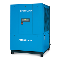
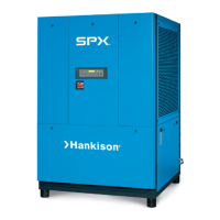
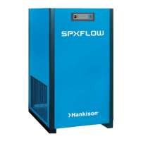
The SPXFLOW FLEX Series Refrigerated Type Compressed Air Dryers are designed to remove moisture from compressed air systems, preventing issues like rust and sludge in manufacturing processes. These dryers utilize a Phase Change Material (PCM) for energy-efficient operation, capable of saving up to 99% of energy at no-load conditions.
Function Description:
The dryers operate by cooling warm, saturated compressed air. Air first enters an air-to-air heat exchanger where it is pre-cooled by outgoing cold, dry air. This pre-cooling condenses up to 65% of the moisture before the air reaches the refrigeration chiller, reducing the heat load on the refrigerant compressor. In the chiller, the air is further cooled, and the condensed moisture is removed by an electronic drain valve. The cold, dry air then passes back through the air-to-air heat exchanger, where it is reheated by the incoming warm air.
The Phase Change Material (PCM) mechanism works as follows:
- When the refrigeration compressor and condenser fan are active, cold refrigerant in the chiller cools the liquid PCM, causing it to solidify.
- Once the PCM is sufficiently cooled and solidified, the compressor and fan stop, and no power is consumed during this period.
- The compressed air is continuously cooled by the solidified PCM.
- As the PCM adsorbs heat from the compressed air, it gradually liquefies. When fully melted, the compressor and fan resume operation to re-cool the PCM.
Important Technical Specifications:
- Models: FLX 1.1, FLX 1.2, FLX 1.5-1, FLX 1.5, FLX 2.1, FLX 2.1-4, FLX 3.1, FLX 4.1, FLX 4.5, FLX 5.5.
- Rated Flow Capacity: Ranges from 75 scfm (FLX 1.1) to 550 scfm (FLX 5.5).
- Inlet/Outlet Connections: NPT 1" for FLX 1.1, FLX 1.2; NPT 2" for all other models.
- Dimensions (H x W x L):
- FLX 1.1: 29.58 x 14.3 x 23.72 inches (751 x 363 x 603 mm)
- FLX 1.2: 28.0 x 14.3 x 30.7 inches (711 x 363 x 781 mm)
- FLX 1.5-1, FLX 1.5, FLX 2.1, FLX 2.1-4: 29.97 x 17.44 x 35.50/37.85 inches (761.2 x 443 x 901.3/961.3 mm)
- FLX 3.1, FLX 4.1: 35.88 x 19.41 x 43.75 inches (911.2 x 493 x 1111.3 mm)
- FLX 4.5, FLX 5.5: 40.61 x 19.43 x 49.32 inches (1031.6 x 493.5 x 1252.8 mm)
- Net Weight: Ranges from 120 lbs (54.5 kg) for FLX 1.1 to 396 lbs (180 kg) for FLX 5.5.
- Electrical Power:
- 115V/1PH/60Hz: FLX 1.1, FLX 1.2, FLX 1.5-1 (0.54-1.04 kW)
- 230V/1PH/60Hz: FLX 1.5, FLX 2.1, FLX 4.1 (0.85-2.54 kW)
- 460V/3PH/60Hz: FLX 2.1-4, FLX 3.1, FLX 4.5, FLX 5.5 (1.26-3.42 kW)
- Refrigerant: R-134a for FLX 1.1, FLX 1.2, FLX 1.5-1, FLX 2.1-4; R-407c for FLX 1.5, FLX 2.1, FLX 3.1, FLX 4.1, FLX 4.5, FLX 5.5.
- Minimum-Maximum Operating Conditions:
- Inlet Air Pressure: 43.5 - 232 psig (3 - 16 barg)
- Inlet Air Temperature: 39°F - 122°F (4°C - 50°C)
- Ambient Temperature: 36°F - 113°F (2°C - 45°C)
- Refrigerant Compressor Control (High Pressure Switch Setting):
- R-134a models (FLX 1.1, FLX 1.2, FLX 2.1-4): Cut-Out 304 psig (21 barg), Manual Reset.
- R-407c models (FLX 1.5-1, FLX 1.5, FLX 2.1, FLX 3.1, FLX 4.1, FLX 4.5, FLX 5.5): Cut-Out 406 psig (28 barg), Manual Reset.
Usage Features:
- Automatic No Loss Drain Valve: Equipped with two electrostatic capacity sensors (high and low level) to selectively discharge condensate, preventing energy loss. The valve attempts to clear blockages and enters alarm mode if unsuccessful after 60 seconds, then cycles every 4 minutes for 5 seconds.
- Controllers:
- Level 1 (FLX 1.1, FLX 1.2): Basic functions including Dryer On/Off, Energy Saving Ratio (%), Alarm Signal, Dryer/Compressor Running Time display, and Dew Point Level indicator.
- Level 2 (FLX 1.5-1 to FLX 5.5): Advanced functions including communication and operating status data storage, with additional features like a Timer Button and Micro-USB connection port.
- Energy Efficiency: Utilizes PCM technology to achieve significant energy savings, especially at no-load conditions.
- Installation: Requires indoor placement, level base, and adequate ventilation (39 inches/1000 mm clearance on sides and front for air-cooled models). Should be located downstream of an aftercooler and mechanical separator. Bypass piping is recommended for uninterrupted airflow during service.
- Safety: Designed with industry-accepted safety factors. Requires qualified personnel for maintenance and adherence to safety rules to avoid voiding warranty or causing injury. Electrical supply must comply with data plate voltage and local codes.
- Operation: Designed for repeated run and stop cycles, preventing freeze-up even with interrupted compressed air demand.
Maintenance Features:
- General: Refrigeration system maintenance should be performed by a competent refrigeration mechanic. Warranty may be voided if unauthorized service is performed.
- Daily Maintenance: Check the operation of the no loss drain valve.
- Monthly Maintenance: Inspect condenser coils and clean with compressed air if necessary (discharge pressure limited to 30 psig).
- Yearly Maintenance: Replace the drain service unit annually. For units with mounted filtration, replace prefilter and afterfilter elements annually.
- Maintenance Kits: Available for various models, including No Loss Drain Valve Repair Kits, Drain Covers, Prefilter Elements, Afterfilter Elements, and Filter Drain Valve Repair Kits.
- Troubleshooting Guide: Provides symptoms, possible causes, and remedies for common issues like water downstream of dryer, high pressure drop, and no condensate from the drain valve.
- Warranty: Two-year warranty on parts and labor from the date of shipment. An extended warranty of up to 5 years may be available. Covers manufacturing defects under normal service conditions; excludes normal wear items and components requiring periodic adjustment or calibration. Unauthorized service voids the warranty.