Diagram
8
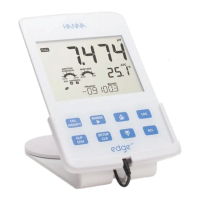
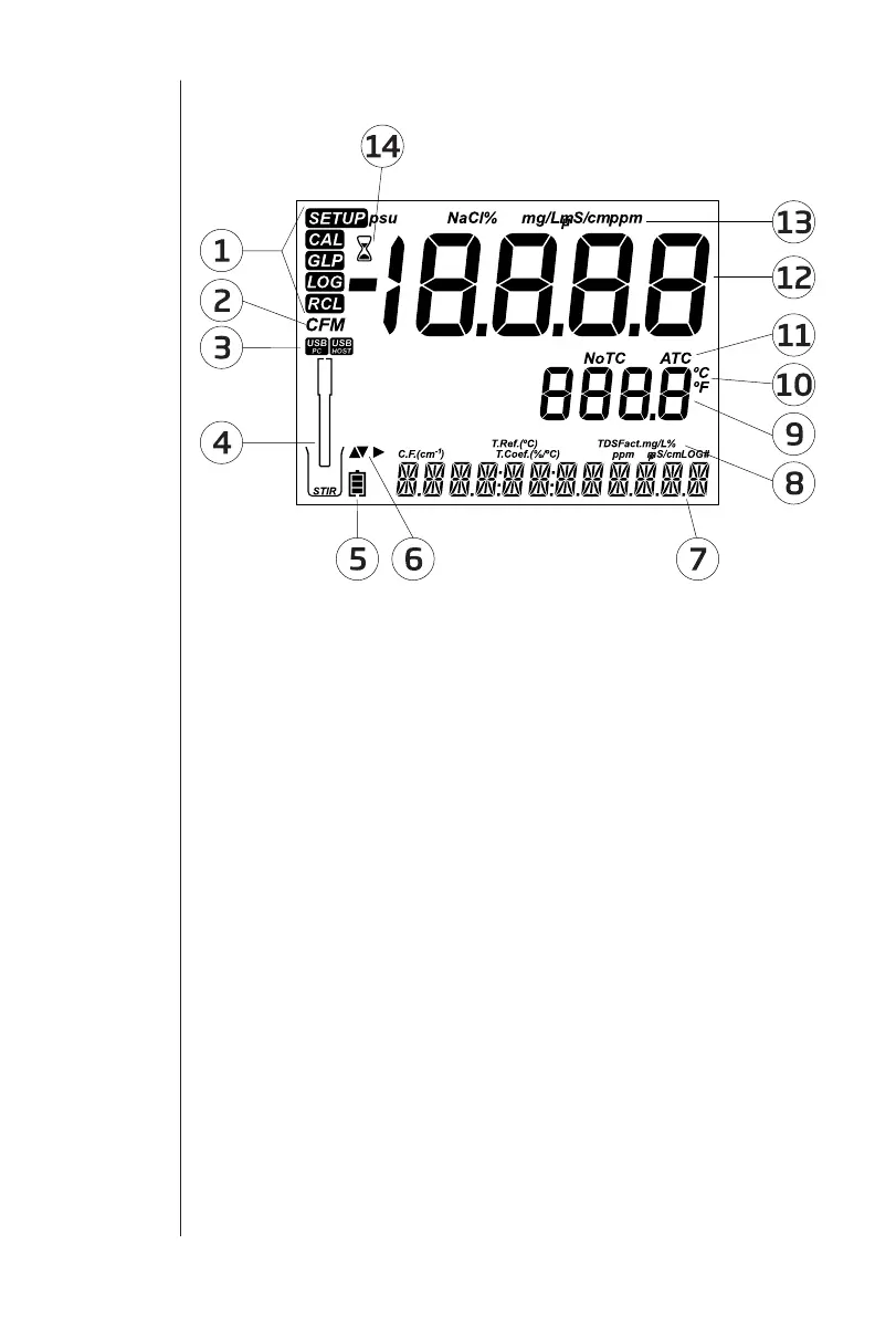
Guide to
Indicators
1. Mode tags
2. Con rm tag
3. USB connection status
4. Probes symbol
5. Battery symbol
6. Arrow tags, displayed when they
are available
7. Third LCD line, message area
8. Labels
9. Second LCD line, temperature
measurement
10. Temperature units
11. Temp. Compensation status
12. Measurement line
13. Measurement units
14. Stability Indicator
The third line of the LCD (9) is a dedicated message line. During measurement
the user may use the pq arrows to select desired message. Options include
date, time, calibration data, battery charge or no message. If a measurement
error or log status change occurs during measurement, the third line will display
a pertinent message.
 Loading...