17
INSTALLATION
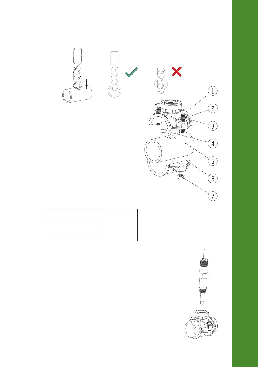
Mounting Recommendations for Saddle
• Select required drill size. See table for dimension details.
Pipe
• Place the upper part of the saddle (3) on top of the
pipe (5) with the seal (4) placed over the hole.
• Take the lower part of the saddle (6), together with
inserted nuts (7) and align it under the upper part.
• Insert the screws (1) with washers (2) through the
holes and tighten by hand into the mounted nuts.
• Using a wrench, tighten all screws carefully.
Saddle for probe & injector Thread size Drill size
Ø 50 mm pipe ½” thread 20 mm - 25.4 mm / 0.79” - 1.00”
Ø 63 mm pipe ½” thread 20 mm - 25.4 mm / 0.79” - 1.00”
Ø 75 mm pipe ½” thread 20 mm - 25.4 mm / 0.79” - 1.00”
Connecting the Probe to the Pump Controller (In-line Configuration)
The probe should be connected to the controller and calibrated before
installation.
To avoid twisting the cable, unplug probe from socket temporarily while
installing in saddle.
Insert the probe and screw it carefully into the saddle, taking care not to
damage the O-ring. Tighten the probe enough to ensure a tight seal.
 Loading...