EasyManua.ls Logo

Hantek 2D82Auto - User Manual

Hantek 2D82Auto
3 pages
Print Icon
To Next Page IconTo Next Page
Loading...
1
GETTING START
Total Menu:
Press this button to enter the total menu, you can choose Vehicle Diagnosis,
Oscilloscope, AWG, DMM, and language switching.
Confirm button:
When setting the source parameter, after entering the character, press the button to
confirm.
Automatically setting button:
It automatically adjust the horizontal and vertical scales of the oscilloscope
automatically and set the trigger coupling, type, position, slope, level and mode,
etc., to acquire a stable waveform display.
Zoom and move keys:
In the trigger menu, the left and down keys push the trigger level down, and the right
and upper direction keys push the trigger level up;
In the channel menu, the upper and lower direction keys change the zero level
position of the channel, and the left and right direction keys change the volt/div of
the channel;
In the time base menu, the upper and lower direction keys change the time/div, and
the left and right direction keys change the horizontal trigger position;
In DMM, switch measurement function;
In generator, after choosing a parameter, the left and lower direction key will reduce
the parameter value, the right and up direction key will increase the parameter
value; it is also used for the digital selection of the virtual keyboard.
Stop and Run:
In scope, stop or run the waveform acquisition;
In DMM, hold the measuring data or update data;
In generator, turn on or off the waveform output.
GETTING START
Question and Answer IconNeed help?

Do you have a question about the Hantek 2D82Auto and is the answer not in the manual?

Summary

Getting Started Overview

Total Menu Navigation

Access and navigate the main menu for device functions like Oscilloscope, AWG, and DMM.

Confirm Button Operation

How to confirm parameter settings after inputting characters in menus.

Automatic Waveform Adjustment

Utilize the auto-set function for automatic horizontal and vertical scale adjustment.

Zoom and Navigation Keys

Understand how to use direction keys for trigger level, channel, and time base adjustments.

Run;Stop and Data Control

Control waveform acquisition, data holding, or generator output.

Power and User Interface

Power Management

Details on using the power key, adapter, and battery charging indicators.

Vehicle Diagnosis Menu

Instructions for accessing and operating the Vehicle Diagnosis menu.

Oscilloscope Display Elements

Identification and explanation of key elements displayed on the oscilloscope screen.

Function Modes and Safety

Digital Multimeter (DMM) Mode

Overview of the DMM interface, including measurement value and type.

Generator Mode Interface

Explanation of the generator's output status, waveform display, and menu access.

General Safety Precautions

Essential safety guidelines for operation, maintenance, and handling the device.

Overview

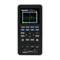
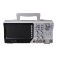
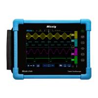
This document describes a multi-functional automotive oscilloscope, designed for vehicle diagnosis, general oscilloscope functions, arbitrary waveform generation (AWG), and digital multimeter (DMM) measurements. It is a portable device with a user-friendly interface, featuring a color display and intuitive controls.

Function Description

The device integrates several key functions:

  • Oscilloscope: This is the primary function, allowing users to visualize and analyze electrical signals over time. It features two input channels (CH1 and CH2) for measuring signals and a dedicated output for a waveform generator (Gen Out). The oscilloscope can automatically adjust horizontal and vertical scales, trigger coupling, type, position, slope, level, and mode to acquire a stable waveform display, simplifying setup for users. It displays trigger status, main time base window, battery level, trigger level, trigger marker, time base, trigger time, channel marker, and coupling/volt/div information for each channel. The main window displays the waveform itself. Users can stop or run waveform acquisition.

  • Vehicle Diagnosis: This specialized mode allows users to select specific test types for automotive systems. The oscilloscope will then automatically configure itself with the corresponding settings for the chosen diagnostic test, streamlining the process for vehicle technicians.

  • Arbitrary Waveform Generator (AWG): The AWG function enables the generation of various waveforms, such as square waves, with adjustable frequency and amplitude. This is useful for testing circuits by injecting known signals. Users can adjust parameters like frequency and amplitude using the device's controls. The output status and waveform display are shown on the screen.

  • Digital Multimeter (DMM): The DMM function provides standard multimeter capabilities, including measuring DC voltage, resistance (OHM), and continuity (Buzzer). It displays the power level, connection diagram, measurement value, and measurement type. In DMM mode, users can switch between different measurement functions and hold or update the displayed data.

Usage Features

The device is designed for ease of use with a combination of physical buttons and on-screen menus:

  • Total Menu: A dedicated "Menu" button provides access to the main menu, where users can select the desired function: Vehicle Diagnosis, Oscilloscope, AWG, DMM, or language switching. Navigation within menus is done using up, down, left, and right direction keys. The up and down keys move the cursor, the left key enters a submenu or function page, and the right key returns to the previous menu.

  • Control Buttons:

    • Scope, DMM, AWG, Menu: These buttons directly access the respective main functions.
    • F1, F2, F3, F4: These are context-sensitive function keys, whose labels change depending on the active menu or screen.
    • Enter (Confirm Key): Used to confirm selections or entered parameters, especially when setting source parameters or character input.
    • Auto (Auto Set Key): Automatically configures the oscilloscope settings for a stable waveform display.
    • Trig (Trigger Menu): Accesses trigger-related settings.
    • Channel (Channel Menu): Accesses channel-related settings.
    • Time (Time Menu): Accesses time base-related settings.
    • Power Key (Run/Stop): Turns the device on/off. In oscilloscope mode, it stops or runs waveform acquisition. In DMM mode, it holds or updates measuring data. In generator mode, it turns on or off the waveform output.
    • Zoom and Move Keys (Directional Arrows): These keys have multiple functions depending on the active mode:
      • In the trigger menu, they adjust the trigger level (left/down for lower, right/up for higher).
      • In the channel menu, they adjust the zero level position (up/down) and volt/div (left/right) of the channel.
      • In the time base menu, they adjust the time/div (up/down) and horizontal trigger position (left/right).
      • In DMM mode, they switch measurement functions.
      • In generator mode, they adjust parameter values (left/down to reduce, right/up to increase) and are used for digital selection on the virtual keyboard.
  • Input/Output Ports:

    • CH1, CH2: Input connectors for measured signals.
    • Gen Out: Output connector for the waveform generator.
    • DMM Input Connector: Dedicated inputs for DMM measurements (A, mA, COM, V/Ω/C).
    • Charging and USB Communication Connector: A Type-C port for power supply, battery charging, and USB communication.

Maintenance Features

The device incorporates features and guidelines for safe operation and basic maintenance:

  • Power Management: The device is powered by a battery and can be charged via a Type-C power adapter (100-240V AC input, 5V@2A output). The power key backlight indicates battery status: red and flashing if no battery is installed, red if the battery is charging, and off when the battery is fully charged. Before starting, users should ensure the battery has sufficient power.

  • General Safety Summary: The manual emphasizes critical safety practices:

    • Qualified Personnel: Maintenance should only be performed by qualified personnel.
    • Fire and Personal Injury Avoidance: Use the specified power cord and ensure proper grounding of the product to prevent electric shock.
    • Probe Connection: Connect probes correctly, ensuring the ground lead is at ground potential.
    • Terminal Ratings: Always check terminal ratings to avoid hazards.
    • Operation with Covers: Do not operate the device with covers or panels removed to avoid contact with exposed circuitry.
    • Suspected Failures: If damage is suspected, have the device inspected by qualified service personnel.
    • Ventilation: Ensure good ventilation.
    • Environmental Conditions: Do not operate in wet/damp environments or explosive atmospheres. Keep surfaces clean and dry.
  • General Inspection: Upon receiving the oscilloscope, users are advised to perform a general inspection:

    • Shipping Container: Check for damage and retain packaging materials until the contents are verified.
    • Accessories: Verify that all listed accessories are present and undamaged.
    • Instrument Check: Inspect the instrument for mechanical damage or defects. If it does not operate properly or fails performance tests, the franchiser should be notified.

Hantek 2D82Auto Specifications

General IconGeneral
Channels2
Record Length / Memory Depth40 kpts
Vertical Resolution8 bits
Trigger ModesEdge, Pulse, Video, Slope, Alternative
MultimeterYes
DMM Diode TestYes
DMM Continuity TestYes
Automotive DiagnosticsYes
Vertical Sensitivity2 mV/div to 10 V/div
Power Supply100-240 VAC, 50/60 Hz
Input Impedance1 MΩ
InterfaceUSB
Sampling Rate250 MSa/s (Single Channel), 125 MSa/s (Dual Channel)
DMM Resolution4.5 digits

Related product manuals