Do you have a question about the Hantek Tablet1000 Series and is the answer not in the manual?
Provides crucial safety precautions to prevent injury and product damage during operation.
Explains safety terms and symbols used in the manual and on the product for hazard identification.
Defines measurement categories for electrical environments and their associated safety implications.
Specifies operating temperature, humidity, altitude, and vibration limits for safe and optimal instrument performance.
Provides instructions on how to maintain and clean the oscilloscope and probes to ensure longevity and performance.
Details WEEE directive compliance and recommendations for equipment recovery and recycling for environmental protection.
Guides users through checking the shipping package, accessories, and the instrument itself upon receiving it.
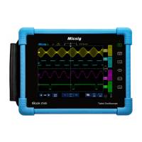
Presents a visual overview and dimensions of the oscilloscope's front panel design.
Provides essential steps for initial setup, including connecting the power supply and ensuring sufficient battery charge.
Details the procedure for starting the instrument after connecting the power supply.
Explains how to select the operating language for the oscilloscope interface.
Describes how to perform a basic functional check and restore default settings.
Outlines the steps for calibrating oscilloscope probes for accurate measurements.
Provides detailed steps and visual guidance for manually compensating the oscilloscope probe.
Introduces the front, rear, side panels, and main interface of the oscilloscope.
Identifies and explains the labels and virtual keys on the oscilloscope's front panel.
Describes the components and features found on the rear panel of the oscilloscope.
Details the multimeter interface and power switch on the right panel, and USB interface on the left panel.
Explains the signal source channel and CH1-CH4 analog input channels on the upper panel.
Illustrates the main interface icons and their functions, including OSC, DMM, AFG, and settings.
Explains the basic touch gestures used for operating the oscilloscope, including touching, kneading, and dragging.
Describes how to use dragging gestures for moving waveform elements and adjusting trigger positions.
Explains how to use the touch screen and virtual keyboard to set instrument parameters.
Details how to input text using the on-screen character keyboard, including uppercase and lowercase letters.
Explains how to input numerical values using the on-screen numeric keypad for parameter settings.
Explains how to adjust the horizontal position of the trigger point and waveform using touch gestures.
Details how to adjust the time value per grid for the horizontal display using buttons or touch gestures.
Describes how to pan and zoom the last collected waveform data after the oscilloscope stops.
Explains how to switch the analog channel function on or off by tapping the channel icon.
Details how to adjust the vertical voltage scale (V/div) for optimal waveform display and measurement.
Explains how to adjust the vertical position of the zero point relative to the screen center using touch gestures.
Describes how to set the coupling mode (DC, AC, Grounded) to filter unwanted signals.
Explains how to use the bandwidth limit feature to reduce noise in the displayed waveform.
Details how to turn on the waveform inversion function to invert the displayed voltage values.
Explains how to manually set the probe attenuation ratio for accurate amplitude measurement results.
Explains how to select the unit for amplitude display, choosing between voltage and current.
Details how to perform addition, subtraction, multiplication, and division on selected data sources.
Explains how to convert time domain signals to frequency domain using FFT analysis with various window functions.
Guides on using cursors to measure frequency and amplitude differences on FFT waveforms.
Details the procedure for saving current waveforms as reference data to internal memory or USB.
Describes how to load and display saved reference waveforms for comparison on the oscilloscope screen.
Describes how to adjust the trigger level voltage to set the trigger point for waveform acquisition.
Explains how to select the input channel (CH1-CH4) as the source for triggering the oscilloscope.
Details the available trigger modes (Normal, Auto, Single, Forced) and their applications.
Explains how to use hold-off time to prevent re-triggering and stably capture complex waveforms.
Details different trigger types available for capturing specific waveform events.
Explains how to set triggers based on rising, falling, or double edges and voltage levels.
Details how to set triggers based on the duration of positive or negative pulses.
Explains how to capture complex video signals using NTSC and PAL standards with specific sync settings.
Details how to set triggers based on the slope (rising/falling) of a signal within a specified time.
Explains how to set triggers when the time interval between edges exceeds a specified timeout period.
Explains how to estimate waveform frequency and amplitude using the grid scale and scale coefficient.
Details how to perform automatic measurements and select from 42 available parameters.
Defines and explains various time-related measurements like period, rise time, fall time, and duty cycle.
Explains parameters related to counting pulses and edges, applicable to analog channels.
Details parameters for measuring time differences and phase shifts between two signal sources.
Explains various voltage measurements including Vmax, Vmin, Vpp, Vtop, Vbase, Vrms, and variance.
Describes how to use vertical and horizontal cursors to measure parameters on the waveform.
Explains how to use the vertical cursor for measuring time and frequency parameters on the waveform.
Explains how to use the horizontal cursor for measuring amplitude parameters on the waveform.
Details the four acquisition modes: Normal, Average, Peak Detection, and High Resolution.
Explains how to set the number of averages to reduce noise when using the Average acquisition mode.
Describes the YT, XY, and Scroll display modes for viewing waveforms.
Explains how memory depth affects waveform point storage and sampling rate.
Details interpolation methods (Sine, Step, Linear) used to reconstruct waveforms from sampled data.
Explains the display types: Vector and Point, for viewing waveforms as connected lines or individual points.
Details afterglow time settings (off, infinite, specific times) for observing waveform changes.
Explains grid types (solid line, none, dots/lines) for the display background.
Describes how to adjust the brightness of the grid lines on the display.
Describes how to adjust the brightness of the displayed waveform.
Explains how to save the display interface as a .bmp image file.
Details saving the oscilloscope waveform data in .lwf format.
Explains how to save the oscilloscope's current settings in a .pho file.
Details saving reference waveforms in .ref format for later comparison.
Explains how to save waveform data in .csv format, noting limitations on export.
Guides users through the menu options for starting or exiting the oscilloscope's self-calibration procedure.
Explains how the Auto setting function recognizes waveform types and optimizes display controls.
Details how to restore the oscilloscope to its factory default settings for options, buttons, and controls.
Lists the available measurement gears: DC/AC voltage, current, resistance, diode, and capacitance.
Guides on selecting voltage measurement modes and connecting probes for accurate readings.
Details the procedure for measuring DC and AC current, including selecting appropriate ranges.
Explains how to measure resistance using the multimeter and correct probe connections.
Guides on measuring capacitance and connecting probes correctly.
Explains how to measure the positive conduction voltage of a diode.
Details how to perform continuity tests using the buzzer function.
Guides on selecting waveform types and setting parameters like frequency, amplitude, offset, and phase.
Explains amplitude (AM) and frequency (FM) modulation, including setting shape, frequency, depth, and offset.
Details how to access the burst menu, set the pulse count, and trigger the corresponding waveform state.
Explains how to use the WaveEditor software to create and edit custom arbitrary waveforms.
Provides methods to download arbitrary waveforms from computer to the oscilloscope via USB.
Details how to open saved pictures from the file browse menu or gallery.
Explains how to open reference waveform files directly in the oscilloscope interface.
Notes that CSV files cannot be called out directly on the machine but can be opened on a computer.
Details how to call out binary files from file browse and view them on the oscilloscope.
Explains how to call out saved settings files and view them on the oscilloscope interface.
Explains how to select the user interface language between English and Chinese.
Displays the machine model, serial number, software, PCB, and FPGA versions.
Details how to adjust touch screen sound and set boot music for the oscilloscope.
Describes how to adjust the screen brightness using a slider control.
Provides steps for upgrading the oscilloscope firmware using a USB storage device.
Explains settings for automatic screen-off time and automatic shutdown time.
Guides on connecting the machine to a computer via USB for file access and sharing.
Details methods for taking screenshots directly or via the Auxiliary > Save menu.
Guides on downloading and installing the necessary IO driver software for remote control.
Troubleshooting steps for when the oscilloscope shows no display after pressing the power button.
Steps to diagnose and resolve issues where no waveform is displayed on the input signal screen.
Guidance for troubleshooting severe distortions in the input signal waveform display.
Troubleshooting steps for waveforms that scroll continuously or fail to trigger properly.
| Sampling Rate | 1GSa/s |
|---|---|
| Bandwidth | 100MHz (Tablet1104) |
| Channels | 2 |
| Memory Depth | 40 Kpts |
| Vertical Resolution | 8 bit |
| Vertical Sensitivity | 2 mV/div - 10 V/div |
| Trigger Type | Edge, Pulse, Video, Slope, Alternative |
| Input Impedance | 1MΩ ± 2% |
| Connectivity | USB |
| Interface | USB |
| Operating Temperature | 0°C ~ +40°C |
| Storage Temperature | -20°C - 60°C |