EasyManua.ls Logo

Hantek DSO1000B Series - User Manual

Hantek DSO1000B Series
84 pages
Print Icon
To Next Page IconTo Next Page
Loading...
V1.6
DSO1000B(V) SERIES
HANDHELD OSCILLOSCOPE
1062B(V)/1102B(V)/1202B(V)
USERS MANUAL

Table of Contents

Question and Answer IconNeed help?

Do you have a question about the Hantek DSO1000B Series and is the answer not in the manual?

Overview

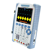
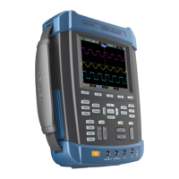
This document describes the DSO1000B(V) Series Handheld Oscilloscope, a versatile device combining oscilloscope and multimeter functionalities.

Function Description

The DSO1000B(V) Series is a digital oscilloscope designed to acquire and display waveforms, analyze signals, and perform various measurements. It also integrates a multimeter for additional electrical measurements. The oscilloscope's primary function is to convert time-domain (YT) signals into their frequency components (spectrum) using Math FFT (Fast Fourier Transform), allowing for the observation and analysis of various signal types.

Important Technical Specifications

Oscilloscope Specifications:

  • Sample Rate Range: 1GS/s
  • Waveform Interpolation: (sin x)/x
  • Record Length: Maximum 1M samples per single-channel; maximum 512K samples per dual-channel (4K, 16K, 40K optional)
  • TIME/DIV Range:
    • DSO1062B(V), DSO1102B(V): 4ns/div to 40s/div, in a 2, 4, 8 sequence
    • DSO1202B(V): 2ns/div to 40s/div, in a 2, 4, 8 sequence
  • Sample Rate and Delay Time Accuracy: ±50ppm over any ≥1ms time interval
  • Delta Time Measurement Accuracy (Full Bandwidth):
    • Single-shot, Normal mode: ± (1 sample interval + 100ppm x reading + 0.6ns)
    • 16 averages: ± (1 sample interval + 100ppm x reading + 0.4ns)

    • Sample interval = s/div ÷ 200
  • Position Range:
    • DSO1062B(V), DSO1102B(V): 4ns/div to 8ns/div (-8div x s/div) to 20ms; 20ns/div to 80µs/div (-8div × s/div) to 40ms; 200µs/div to 40s/div (-8div x s/div) to 400s
    • DSO1202B(V): 2ns/div to 10ns/div (-4div × s/div) to 20ms
  • A/D Converter: 8-bit resolution, each channel sampled simultaneously
  • VOLTS Range: 2mV/div to 5V/div at input BNC
  • Position Range (Vertical): 2mV/div to 200mV/div, ±2V; >200mV/div to 5V/div, ±50V
  • Analog Bandwidth in Normal and Average modes at BNC or with probe, DC Coupled: 2mV/div to 200mV/div, ±2V; 50mV/div to 2V/div, ±40V; 5V/div, ±50V
  • Selectable Analog Bandwidth Limit, typical: 20MHz
  • Low Frequency Response (-3db): ≤10Hz at BNC
  • Rise Time at BNC, typical:
    • DSO1062B(V): <5.8ns
    • DSO1102B(V): <3.5ns
    • DSO1202B(V): <1.8ns
  • DC Gain Accuracy: ±3% for Normal or Average acquisition mode, 5mV/div to 10V/div; ±4% for Normal or Average acquisition mode, 5mV/div to 2mV/div
  • DC Measurement Accuracy, Average Acquisition Mode: Measurement Type: Average of ≥16 waveforms with vertical position at zero. Accuracy: ± (3% × reading + 0.1div + 1mV) when 10mV/div or greater is selected. Measurement Type: Average of ≥16 waveforms with vertical position not at zero. Accuracy: ± [3% × (reading + vertical position) + 1% of vertical position + 0.2div]. Add 2mV for settings from 2mV/div to 200mV/div; add 200mV for settings from 200mV/div to 5V/div.
  • Volts Measurement Repeatability, Average Acquisition Mode: Delta volts between any two averages of ≥16 waveforms acquired under same setup and ambient conditions.
  • Trigger Sensitivity (Edge Trigger Type):
    • DSO1062B(V): 1div from DC to 10MHz; 1.5div from 10MHz to Full
    • DSO1102B(V): 1div from DC to 10MHz; 1.5div from 10MHz to Full
    • DSO1202B(V): 1div from DC to 10MHz; 2div from 100MHz to Full
  • Trigger Level Range: ±8 divisions from center of screen
  • Trigger Level Accuracy, typical: 0.2div x volts/div within ±4 divisions from center of screen (for signals having rise and fall times ≥20ns)
  • Holdoff Range: 100ns to 10s
  • Pulse Width Range: Selectable from 20ns to 10s
  • Overtime Trigger Time Range: Selectable from 20ns to 10.0sec
  • Trigger Frequency Counter: 6 digits
  • Frequency Range (Trigger): AC coupled, from 4Hz minimum to rated bandwidth
  • Input Impedance: 1MΩ±2% in parallel with 20pF±3pF
  • Probe Attenuation: 1X, 10X
  • Maximum Input Voltage: 300VRMS (10×), Installation Category II; derate at 20dB/decade above 100kHz to 13V peak AC at 3MHz* and above. Peak value must be less than 450V. Excursion above 300V should be of less than 100ms duration. RMS signal level including all DC components removed through AC coupling must be limited to 300V.
  • Display Type: 5.6 Inch width TFT Display
  • Display Resolution: 480 (Vertical) X 640 (Horizontal) pixels
  • Display Contrast: Adjustable (16 gears) with the progress bar
  • Probe Compensator Output: About 5Vpp into ≥1MΩ load, 1kHz
  • Power Supply: AC Input: 100-240VACRMS, 0.6A MAX, 50Hz/60Hz; DC Output: 12V, 2A; DC Input: DC8.5-15V, 2A
  • Power Consumption: <30W
  • Battery Type: 7.4V
  • Size (Mechanical): Length: 245mm, Height: 163mm, Depth: 52mm
  • Weight: 1.2 Kg
  • Operating Temperature: 32°F to 122°F (0°C to 50°C)
  • Nonoperating Temperature: -40°F to 159.8°F (-40°C to +71℃)
  • Operating Humidity: +104°F or below (+40°C or below): ≤90% relative humidity; 106°F to 122°F (+41°C to 50°C): ≤60% relative humidity
  • Altitude: Operating and Nonoperating: 3,000m (10,000 feet)
  • Random Vibration: Operating: 0.31gRMS from 50Hz to 500Hz, 10 minutes on each axis; Nonoperating: 2.46gRMS from 5Hz to 500Hz, 10 minutes on each axis
  • Mechanical Shock: 50g, 11ms, half sine

Multimeter Specifications:

  • Maximum Resolution: 6000 Counts
  • DMM Testing Modes: Voltage, Current, Resistance, Capacitance, Diode & Continuity
  • Maximum Input Voltage: AC: 600V, DC: 800V
  • Maximum Input Current: AC: 10A, DC: 10A
  • Input Impedance: 10MΩ
  • DC Voltage Range: 60.00mV (manual) to 800V, Accuracy: ±1%±1digit, Resolution: 10uV to 1V
  • AC Voltage Range: 60.00mV (manual) to 600.0V, Accuracy: ±1%±3digit, Resolution: 10uV to 100mV
  • DC Current Range: 60.00mA to 10.00A, Accuracy: ±1.5%±1digit to ±1.5%±3digit, Resolution: 10uA to 10mA
  • AC Current Range: 60.00mA to 10.00A, Accuracy: ±1.5%±3digit, Resolution: 10uA to 10mA
  • Resistance Range: 600.0Ω to 6.000MΩ, Accuracy: ±1%±1digit, Resolution: 0.1Ω to 1KΩ
  • Capacitance Range: 40.00nF to 400.0uF, Accuracy: ±1%±1digit, Resolution: 10pF to 100nF (Smallest measurable capacitance is 5nF)
  • Diode: 0V-2.0V
  • On-off Test: < 30Ω

Usage Features

Oscilloscope Operation:

  • Autoset: Automatically adjusts horizontal and vertical scales, trigger coupling, type, position, slope, level, and mode for a stable waveform display.
  • Triggering: Supports various trigger types including Edge, Video, Pulse Width, Slope, Overtime, and Alter.
    • Edge Trigger: Triggers on a specified level crossing in a particular direction.
    • Video Trigger: Performs field or line triggers for standard video signals (NTSC, PAL, SECAM).
    • Pulse Width Trigger: Triggers on pulses meeting specific width conditions, useful for aberrant pulses.
    • Slope Trigger: Triggers based on the rise or fall times of a signal, offering more flexibility than edge triggering.
    • Overtime Trigger: Triggers after a signal edge reaches a set time, useful for long pulse signals.
    • Alter Trigger: Provides stable displays for signals with two different frequencies by switching between CH1 and CH2.
    • Trigger Coupling: Determines which part of the signal is delivered to the trigger circuit (AC, DC, Noise Reject, HF Reject, LF Reject).
    • Trigger Holdoff: Allows setting a time interval between triggers to stabilize complex waveforms like pulse trains.
  • Data Acquisition: Offers Real-time and Equivalent acquisition modes.
    • Real-time Acquisition Modes:
      • Normal: Samples signals at evenly spaced intervals, suitable for most signals.
      • Peak Detect: Captures maximum and minimum values, useful for detecting glitches and limiting aliasing.
      • Average: Reduces random noise by averaging multiple waveforms.
  • Waveform Scaling and Positioning: Allows adjustment of horizontal and vertical scales and positions to optimize waveform display.
  • Waveform Measurement: Supports both cursor measurements (amplitude in dB, frequency in Hz) and automatic measurements (Frequency, Period, Mean, Pk-Pk, Cycle RMS, PRMS, Min, Max, Rise Time, Fall Time, + Width, - Width, + Duty, - Duty, Base, Top, Middle, Amplitude, Overshoot, Preshoot, Pmean, FOVShoot, RPREShoot, BWidth, Delay 1-2 ↑, Delay 1-2 ↓, LFF, LFR, LRF, LRR, FFR, EFRF).
  • Display Area: Supports YT, XY, Vectors, and Dots display formats. Includes indicators for acquisition mode, trigger status, and tool icons (keyboard lock, USB disk connection, USB slave interface).
  • Math Functions: Performs waveform math operations such as CH1+CH2, CH1-CH2, CH2-CH1, CH1XCH2, CH1/CH2, CH2/CH1, and FFT.
    • Math FFT (Fast Fourier Transform): Converts time-domain signals into frequency components (spectrum) for analyzing harmonics, distortion, noise, impulse response, and vibration. Offers Hanning, Flattop, and Rectangular window types. Includes options for horizontal and vertical zoom and cursor measurements on the FFT spectrum.
  • Save/Recall: Saves and recalls oscilloscope setups and waveforms (Wave, Setup, CSV formats) to local memory or USB disk.
  • Video Playback: (DSO1000BV only) Supports playing various video and audio file formats (mpg, avi, flv, mp3, vob, wmv, swf, mp4) from a U disk, with resolutions up to 640x480.
  • Network Settings: Allows setting Device IP and Device Port for network configuration.

Multimeter Operation:

  • Measurement Modes: DC/AC voltage, DC/AC current, resistance, capacitance, diode test, and on-off measurement.
  • Range Adjustment: Supports both automatic and manual range selection.
  • Relative Measurement: Displays a measured result relative to a defined reference value.

Maintenance Features

  • Installation: Requires at least 5cm space around the top and sides for proper ventilation.
  • Functional Check: A quick procedure to verify basic functionality upon startup.
  • Probe Examination: Includes safety guidelines and a "Probe Check Wizard" for proper probe compensation.
  • Manual Probe Compensation: Steps to manually compensate probes for accurate measurements.
  • Probe Attenuation Setting: Guides on setting probe attenuation (1X, 10X) and its impact on bandwidth.
  • Self Calibration: A routine to optimize oscilloscope signal path for maximum measurement accuracy, recommended after operating temperature changes by more than 5°C and after 20 minutes of warm-up.
  • Troubleshooting: Provides guidance for common issues like power-on failures, no waveform display, distorted waveforms, and unstable triggers.
  • General Care: Avoid direct sunlight exposure for the LCD. Do not expose to sprays, liquids, or solvents.
  • Cleaning: Use a lint-free cloth for dust removal. Clean with a soft cloth dampened with water or a 75% isopropyl alcohol solution. Avoid corrosive or chemical cleaning agents.
  • Battery Charging: The battery is partially charged at the factory. It can be charged while the device is on or off (5 hours when off, 12 hours when on).
  • Backlight Control: Adjustable backlight settings.
  • Auto Shut Down: Configurable automatic shutdown to conserve power.

Hantek DSO1000B Series Specifications

General IconGeneral
BrandHantek
ModelDSO1000B Series
CategoryTest Equipment
LanguageEnglish

Related product manuals