Main Feature Description
DSO5000P Series Digital Storage Oscilloscope User Manual 10
trigger channel or the AC power line (only for Edge triggers). The source with the AC power line
shows the frequency relationship between the signal and the AC commercial power.
Trigger Type: The oscilloscope has six types of triggers: Edge, Video, Pulse Width, Slope,
Overtime and Swap.
Edge Trigger uses the analog or digital test circuits for triggering. It happens when the
input trigger source crosses a specified level in a specified direction.
Video Trigger performs a field or line trigger through standard video signals.
Pulse Width Trigger can trigger normal or abnormal pulses that meet trigger conditions.
Slope Trigger uses the rise and fall times on the edge of signal for triggering.
Overtime Trigger happens after the edge of signal reaches the set time.
Swap Trigger, as a feature of analog oscilloscopes, gives stable displays of signals at
two different frequencies. Mainly it uses a specific frequency to switch between two
analog channels CH1 and CH2 so that the channels will generate swap trigger signals
through the trigger circuitry.
Trigger Mode: You can select the Auto or Normal mode to define how the oscilloscope acquires
data when it does not detect a trigger condition. Auto Mode performs the acquisition freely in
absence of valid trigger. It allows the generation of untriggered waveforms with the time base set
to 80ms/div or slower. Normal Mode updates the displayed waveforms only when the
oscilloscope detects a valid trigger condition. Before this update, the oscilloscope still displays the
old waveforms. This mode shall be used when you want to only view the effectively triggered
waveforms. In this mode, the oscilloscope displays waveforms only after the first trigger. To
perform a single sequence acquisition, push the SINGLE SEQ button.
Trigger Coupling: Trigger Coupling determines which part of the signal will be delivered to the
trigger circuit. This can help to obtain a stable display of the waveform. To use trigger coupling,
push the TRIG MENU button, select an Edge or Pulse trigger, and then select a Coupling option.
Trigger Position: The horizontal position control establishes the time between the trigger position
and the screen center.
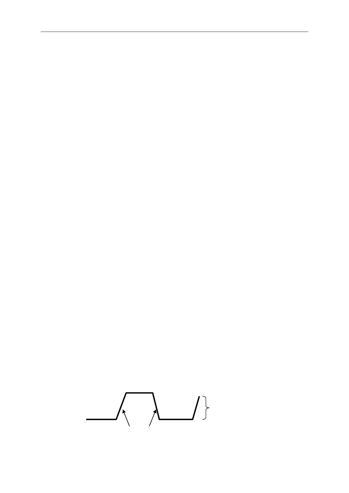
Slope and Level: The Slope and Level controls help to define the trigger. The Slope option
determines whether the trigger point is on the rising or falling edge of a signal. To perform the
trigger slope control, press the TRIG MENU button, select an Edge trigger, and use the Slope
button to select rising or falling. The TRIGGER LEVEL knob controls the trigger point is on which
position of the edge.
Trigger slope can be rising or falling
Trigger level can be
adjusted vertically