Do you have a question about the Hantek HT8000 Series and is the answer not in the manual?
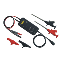
The Hantek HT8000 Series High Voltage Isolating Probes are designed for measuring high voltages and providing isolation from ground, making them suitable for a variety of applications where safety and accuracy are paramount. These probes utilize a differential input mode, which is crucial for measurements in environments where a direct connection to ground is not feasible or desirable. The design emphasizes stability, reliability, and accuracy, ensuring consistent performance across different measurement scenarios.
A key function of the HT8000 Series probes is their ability to offer two selectable attenuation ranges: 1/50 and 1/500. This flexibility allows users to adapt the probe to different voltage levels, with maximum measurable differential voltages of 130V (DC + peak AC) for the 1/50 range and 1300V (DC + peak AC) for the 1/500 range. This dual-range capability enhances the versatility of the probes, enabling them to handle a broad spectrum of high-voltage measurements.
The probes are equipped with an over-range alarm function, indicated by a red LED. This feature serves as a critical safety and operational alert, notifying the user when the measured voltage exceeds the selected range. This helps prevent potential damage to the probe and ensures the integrity of the measurement. A green POWER indicator light also provides immediate visual confirmation that the probe is receiving power and is operational.
The HT8000 Series probes are designed to be compact and robust, making them suitable for use in various industrial and laboratory settings. Their small form factor contributes to ease of handling and integration into existing test setups. The construction is geared towards durability, ensuring a long operational life even in demanding environments.
These high-voltage isolating probes find application in numerous fields, particularly where measurements without a direct ground connection are required, or where high voltage and strong electricity are present. Specific usage scenarios include:
For optimal use, the probes come with a set of accessories, including an AC adapter, a couple of alligator clips, and a couple of pincer clips. These accessories are designed to facilitate secure and reliable connections to the circuit under test, enhancing the overall usability and safety of the product. The input and output cables are of specific lengths, chosen to balance convenience with signal integrity, minimizing noise and errors.
Operating the HT8000 Series probes is straightforward, but adherence to the instruction manual is strongly recommended, especially for new users, to ensure safety and prevent damage. The operational steps emphasize a logical sequence of connections and disconnections to safeguard both the user and the equipment.
Before connecting the AC adapter, it is crucial to verify that the line voltage matches the specified input range (AC100V~240V, 50~60Hz) to prevent damage. The instruction manual explicitly warns against using an unspecified AC adapter.
When preparing for a measurement, users should first estimate the voltage to be measured and set the appropriate attenuation switch (1/50 or 1/500). Incorrect attenuation settings can lead to over-range conditions, indicated by the red LED, and potentially damage the probe. The BNC output terminal should be connected to an oscilloscope or other measuring instrument, and the input cables should be securely connected to the adapt clips.
The probe body should be kept away from high-voltage pulse circuits during measurements to minimize noise and errors, ensuring the accuracy of the readings. Once the test is complete, the power should be disconnected first, followed by disconnecting the input from the measured target, and finally, disconnecting the output BNC terminal from the measuring instrument. This sequence is vital for safety.
A specific attention point for usage involves twisting the input leads. This practice helps to cancel noise induced into the leads and improves the high-frequency response of the inputs, leading to more accurate measurements. Users are also advised against unnecessarily extending input cables, as this can introduce more noise. If extension is unavoidable, the extended cables should be of the same length, and the measured signal frequency should ideally be below 10MHz to avoid significant errors.
For high-accuracy measurements, it is recommended to allow the probe and the measuring instrument to warm up for 20 minutes. This ensures that the internal components reach a stable operating temperature, contributing to more precise results.
Maintenance features primarily revolve around proper handling and troubleshooting. The manual provides guidance on common issues, such as the power LED not illuminating, which points to checking the AC adapter and its connection. If the measured waveform is not displayed correctly or lacks stability, troubleshooting steps include verifying the probe accessories, checking the probe connection to the circuit, performing a functional check on the probe, or even trying a different channel on the oscilloscope or a different oscilloscope altogether. These steps help users diagnose and resolve common operational problems, ensuring the longevity and reliable performance of the HT8000 Series probes.
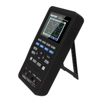
| Type | Digital Oscilloscope |
|---|---|
| Bandwidth | 200 MHz |
| Display | 7-inch TFT LCD |
| Input Voltage Range | 400 V (DC + AC peak) |
| Record Length | 40 Kpts |
| Vertical Resolution | 8-bit |
| Timebase Range | 5 ns/div - 50 s/div |
| Trigger Modes | Edge, Pulse, Video, Slope, Alternate |
| Interface | USB |
| Power Supply | 100V - 240V AC, 50/60Hz |