Do you have a question about the Hantek 1832C and is the answer not in the manual?
Guidelines for safe operation and use of the instrument, including environmental conditions and component handling.
Explanation of warning symbols used in the manual to alert users to potential hazards or important procedures.
Covers environment, test fixture use, warm-up, and initial general inspection for safe operation.
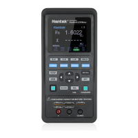
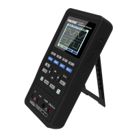
Description of the instrument's front panel layout and the function of each key and display element.
Explanation of the instrument's measurement and system settings interfaces, including display elements and icons.
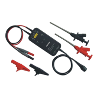
Details about the 3-terminal and 5-terminal test ports used for connecting components and ensuring measurement accuracy.
Procedure for powering the instrument on and off, and the initial measurement interface display.
Methods to change the AC test signal frequency for measurements.
Methods to change the AC test signal level for measurements.
Methods to select the appropriate measurement range for components.
Methods to adjust the measurement speed (Fast, Medium, Slow).
How to select the primary measurement parameter (R, L, C, Z, Auto).
How to select the secondary measurement parameter (X, Q, D, ESR, Theta).
Procedure for setting the nominal value and tolerance for comparator function.
Selecting between series (SER) and parallel (PAL) equivalent circuit models for accurate measurements.
Using the relative mode to set a reference value for measurements.
How to freeze the displayed measurement data on the LCD.
Using the data recording mode to acquire maximum, minimum, or average readings.
Procedure for open and short circuit correction to reduce measurement errors.
Steps for downloading the tool and updating the instrument's firmware.
Step-by-step guide for measuring resistance using the instrument, including connection and parameter setup.
Step-by-step guide for measuring capacitance, emphasizing capacitor discharge before measurement.
Step-by-step guide for measuring inductance, including connection and parameter setup.
Step-by-step guide for measuring impedance, including connection and parameter setup.
Instructions for connecting the handheld LCR meter to a PC via USB for control and data acquisition.
Details on data types, grammar, symbols, abbreviations, capitalization, and error codes for commands.
Defines the characters that can be used to terminate commands sent to the instrument.
Description of universal public commands like *IDN? and *GTL used for instrument interaction.
Overview of subsystem commands for frequency, function, and fetch operations.
Overview of the instrument's general specifications, including model, parameters, modes, speed, and interfaces.
Detailed accuracy specifications for capacitance, resistance, inductance, impedance, and phase angle measurements under various conditions.
Accuracy tables for Capacitance (C) and Dissipation Factor (D) across different frequencies and ranges.
Accuracy tables for Inductance (L) and Quality Factor (Q) across different frequencies and ranges.
Accuracy tables for Impedance (Z) and Phase Angle (θ) across different frequencies and ranges.
Troubleshooting steps for equipment failure, including battery, power jack, test accessories, and contacting service.
Instructions for safely cleaning the instrument, including precautions and cleaning agents.
List of standard accessories included with the handheld LCR meter and instructions for checking contents.
| Sample Rate | 1 GSa/s |
|---|---|
| Channels | 2 |
| Connectivity | USB, LAN |
| Vertical Sensitivity | 2 mV/div to 10 V/div |
| Time Base | 5 ns/div to 50 s/div |
| Display | 7 inch LCD |
| Trigger Modes | Edge, Pulse, Video |
| RBW | 1 Hz to 1 MHz |
| Input Impedance | 1 MΩ |
| Input Coupling | AC, DC, GND |
| Operating System | Linux |
| Probe Attenuation | 1X, 10X |