Do you have a question about the Hantek Hantek2000 Series and is the answer not in the manual?
Comprehensive safety guidelines for operating the oscilloscope to prevent hazards and ensure proper use.
Explanation of terms (Danger, Warning) and symbols used on the product for safety.
Recommendations for proper device recycling to minimize environmental impact.
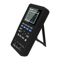
Highlights key features like design, display, sampling rate, and connectivity.
Covers front panel, user interface, initial inspection, and probe checks.
Details button functions, navigation keys, and input/output connectors.
Describes waveform display components and system status indicators.
Steps for checking shipping container, accessories, and instrument condition.
Procedures for powering on and performing a basic functional test.
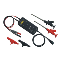
Safety guidelines and manual compensation steps for oscilloscope probes.
Adjusting probe capacitance and verifying waveform shape.
How probe attenuation affects vertical scale and bandwidth.
Overview of Menu/Keys, Connectors, Auto Set, Defaults, Horizontal, Vertical, Trigger, Save, Reference, Measurement, Utility.
Explains mode selection, navigation, directional, and multi-function keys.
Identifies signal input/output, charging, data, and DMM terminals.
How the Auto set button identifies and adjusts for waveform display.
Explains how Auto Set determines the trigger source based on signal conditions.
Steps to restore the oscilloscope to its factory default settings.
Lists default settings for parameters like Cursor, Display, Horizontal, Trigger.
Lists configuration options that remain unchanged upon recalling defaults.
Adjusting horizontal time scale (SEC/DIV) and trigger position.
Explains Y-T, Roll, and Scan modes for waveform display.
Adjusting vertical position and VOLTS/DIV for selected channels.
Details On/Off, Coupling, Probe attenuation, and Bandwidth Limit settings.
Explains trigger source, mode, level, and slope for waveform stabilization.
Detailed explanation of trigger source, mode (Auto/Normal), and Force Trigger.
Steps to save waveform data and current state settings, and how to recall them.
Using REF channel to compare waveforms and saving reference waveforms.
Using graticule and cursors for waveform measurements.
Setting up, moving, and reading cursor measurements.
Explains automatic measurements for frequency and amplitude.
Covers language, sound, backlight, shutdown, system info, and calibration.
How to update the oscilloscope firmware via a USB connection.
Configuring custom shortcuts and recalling saved settings.
Using shortcut keys for quick data saving.
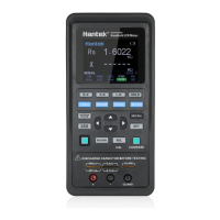
Overview of DMM interface and supported measurements (voltage, current, etc.).
Step-by-step guide for measuring DC and AC voltage.
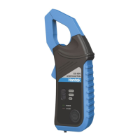
Instructions for measuring current, resistance, capacitance, and diodes.
How to perform continuity tests using the DMM.
Using the hold button to retain the displayed measurement value.
Overview of Generator interface and setting signal type, frequency, and amplitude.
Adjusting output waveform offset, duty cycle, and generating arbitrary waveforms.
Turning the signal output on or off using the output button.
Diagnosing and resolving power-on failures and no waveform display.
Troubleshooting distorted waveforms and continuous rolling without triggering.
Advice on device care, avoiding sunlight, and cleaning procedures.
Details on Bandwidth, Sample Rate, Volt/Div, Acquisition Modes, and Trigger Type.
Covers Trigger Mode, Input Impedance, Measurement types, Display, and Power.
Details Operating Temperature, Humidity, Altitude, and Mechanical Shock.
Details on Waveform Frequency, Sampling, Amplitude, and Resolution.
Specifies DMM maximum resolution and input voltage/current limits.
Details accuracy and resolution for DC/AC voltage and current measurements.
Provides accuracy and resolution for resistance and capacitance measurements.
Lists all standard accessories included with the oscilloscope.
| Sample Rate | 1GSa/s |
|---|---|
| Trigger Type | Edge, Pulse, Video, Slope, Alternate |
| Trigger Modes | Auto, Normal, Single |
| Interface | USB host, USB device |
| Bandwidth | 200 MHz |
| Vertical Resolution | 8 bit |
| Time Base Range | 5 ns/div to 50 s/div |
| Time Base | 5 ns/div to 50 s/div |
| Display | 7 inch LCD |
| Display Type | TFT LCD |
| Power Supply | 100-240 VAC, 50/60 Hz |
| Input Impedance | 1MΩ ± 2%, in parallel with 20pF |
| Vertical Sensitivity | 2mV/div ~ 10V/div |