CLOSEMOUNT STYLE FAN MOUNTING
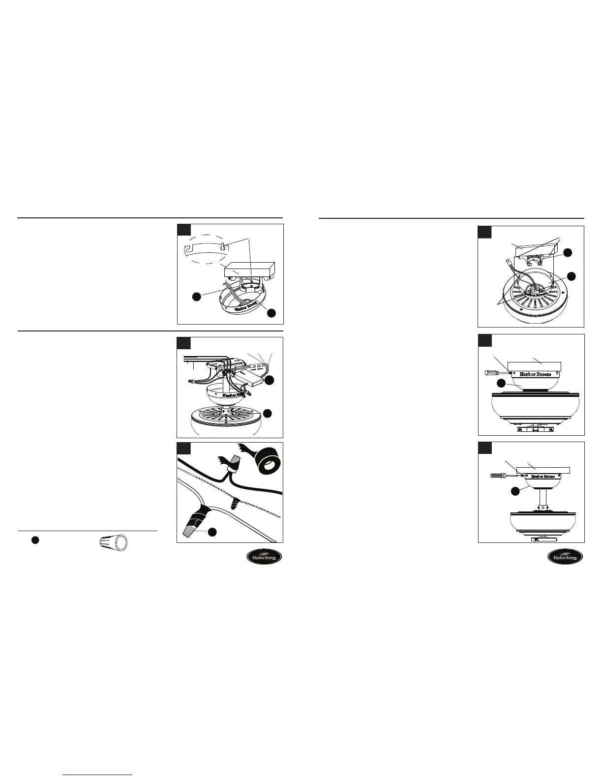
4. Temporarily hang the canopy (B) onto the hook
on the mounting bracket (A) using one of the
non-slotted holes in the canopy (B). This will
allow for hands-free wiring.
4
A
B
Hook
10 11
Page 10 Page 11
WIRING
Hardware Used
1. Insert receiver from the remote pack (K) into
mountingbracket(A)withtheatsidetowardthe
ceiling. Connect the GREEN/GROUND wire from
fan to the BARE/GREEN supply wire. Connect
the BLACK wire (AC IN L) from the receiver to the
supply BLACK wire. Connect the WHITE wire (AC
IN N) from receiver to the supply WHITE WIRE.
Connect FEMALE plug from the receiver to the
MALE plug from the top of motor assembly (E) or
MALE plug of lead wire (L) if previously installed.
2. Twist wire ends together and screw wire connectors
(AA) on in a clockwise direction. Tape wire
connectors (AA) and wires together with electrical
tape (not included).
WARNING: Be sure no bare wire or wire strands are
visible after making connection. Place GREEN and
WHITE connections on opposite side of box from
the BLACK and BLUE (if applicable) connections.
The splices should be turned upward and pushed
carefully up into the outlet box.
1
2
x 3
Wire Connector
AA
E
Black
White
Ground/Green
Ground/Green
White
White
Blue Black
Black
K
NOTE: BLACK wire is hot power for fan. WHITE
wire is common for fan and light kit. GREEN wire
is ground wire. If house wires are different colors
than referred to above, stop immediately. Consult
a licensed electrician to determine proper wiring.
FINAL INSTALLATION
You may now proceed to Step 4.
3. Directly align the locking slots of the canopy (B) with
the two screws previously loosened (step 3, page 6)
in the mounting bracket (A). Push up to engage the
slots and turn clockwise to lock in place. Immediately
tightenthetwoscrewsrmly,thenre-installthetwo
screws that were previously removed (step 3, page 6)
to fully secure the canopy (B) to the mounting bracket
(A).
2. Re-install the two screws that were previously removed
(step 3, page 6) to fully secure the canopy (B) to the
mounting bracket (A).
If you installed the fan with “Closemount Style Fan
Mounting”, continue to Steps 1 and 2. If you installed
the fan with “Downrod Style Fan Mounting”, skip to
Step 3.
1. Remove the fan from the hook on the mounting
bracket (A). Align the locking slots of the canopy
(B) with the two screws previously loosened (step
3, page 6) in the mounting bracket (A). Push up to
engage the slots and turn clockwise to lock in place.
Immediatelytightenthetwoscrewsrmly.
1
Locking
slots
Outlet
box
Screws
hook
B
A
Outlet box
Screw
B
2
Outlet box
Screw
B
3
Lowes.com/harborbreeze Lowes.com/harborbreeze
 Loading...