WIRING (continued from previous page)
7
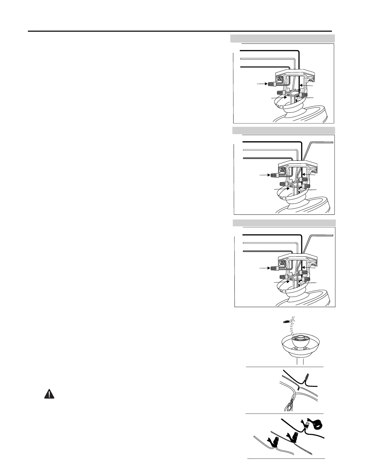
2. Connect green wire from downrod (A) to green wire on mounting
bracket (C). [Fig. 2]
3. Strip 3/4 of an inch of insulation from ends of white wire. Twist
stripped ends of each strand of wire within the insulation with
pliers. [Fig. 3] Snip ends after twisting strands together. Repeat for
black, blue (if applicable) and green wires.
4. Screw wire connectors (O) on in a clockwise direction. Wrap
electrical tape around each individual wire connector (O) down to
the wire as shown in Fig. 4.
Warning: Make sure no bare wire or wire strands are visible
after making connections. Place green and white connections on
opposite side of box from the black and blue (if applicable)
connections.
Turn spliced/taped wires upward and gently push wires and wire
connectors (O) into outlet box.
Fig. 2
Fig. 3
Fig. 4
B
A
O
O
O
Note: Black wire is hot power for fan. Blue wire is hot power for
light kit. White wire is common for fan and light kit. Green or bare
wire is ground.
FAN AND LIGHT CONTROLLED BY SEPARATE WALL SWITCHES.
Fig. 1C
SWITCHED FAN POWER
WHITE (NEUTRAL)
GROUND
BLACK
WHITE
GROUND
SWITCHED
LIGHT
POWER
BLUE
FAN CONTROLLED BY CHAIN, LIGHT BY WALL SWITCH.
Fig. 1B
BLACK (POWER)
WHITE (NEUTRAL)
GROUND
BLACK
WHITE
GROUND
SWITCHED
LIGHT
POWER
BLUE
Fig. 1A
FAN AND LIGHT CONTROLLED BY CHAIN.
BLACK (POWER)
WHITE (NEUTRAL)
GROUND
BLACK
WHITE
BLUE
GROUND
1. Choose wiring diagram [Fig. 1A, Fig. 1B or Fig. 1C] that fits your
situation and make appropriate wiring connections as follows:
(Make special note of Step 3 below while wiring.)
1A. Connect BLACK and BLUE wire from fan to BLACK wire
from ceiling with wire connector (O) provided. Connect WHITE
wire from fan to WHITE wire from ceiling with wire connector (O)
provided. Connect all GROUND (GREEN) wires together from
fan to BARE/GREEN wire from ceiling with wire connector (O)
provided. [Fig. 1A]
1B. If you intend to control the fan light with a separate wall
switch, wire as indicated in the instructions in 1A except connect
BLUE wire from fan to the BLACK supply from the independent
switch. [Fig. 1B]
1C. If you intend to control the fan and light with separate wall
switches, wire as indicated in the instructions in 1A except
connect BLUE wire from fan to the BLACK supply from the
independent wall switch for the light and connect BLACK wire
from fan to the BLACK supply from the other independent wall
switch for the fan. [Fig. 1C]