EZ-Guide® Plus
Mounting the lightbar
Caution — The suction cup mount is a temporary mounting device. Before you use it,
read the manufacturer’s instructions provided with the mounting kit.
1. Dampen the rubber seal on the suction cup.
2. Place the suction cup on a clean section of window, and then pump the plunger until its red line is no longer visible.
In addition:
• To ensure that the lightbar stays securely attached, pump the suction cup each day, or whenever the red line appears
on the plunger.
• If the lightbar does not stay securely attached with the suction cup, you can glue the cup to the window. Or, attach the
lightbar bracket directly to the dash, ceiling, or window.
Using the vehicle cigarette lighter
If the power cable is plugged into a cigarette lighter that is not wired through the vehicle ignition, the lightbar receives
power whenever the cable is plugged in. To avoid draining the vehicle battery, turn off or disconnect the lightbar from
the power source if the vehicle will be unused for an extended time.
Minimizing GPS signal interference
o minimize any interference to the GPS signal, make sure that the GPS antenna is at least 1 m (3 ft) from any other
antenna (including a radio antenna), and at least 100 m (300 ft) from any power line, radar dish, or cell phone tower.
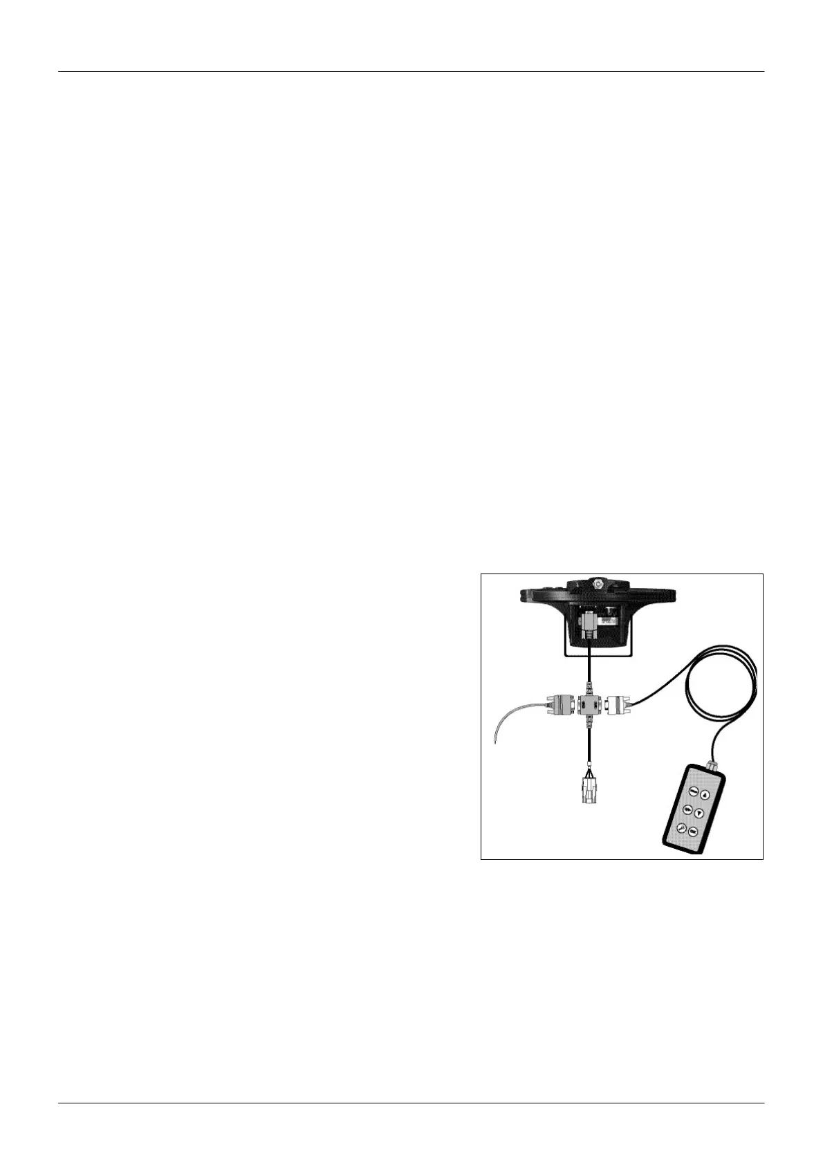
Connecting other devices
• To use the remote control or an external GPS receiver or an exter- na
sensor (for example, yield monitor), attach it directly to the lightbar
data port connector.
• To use the remote control and an external receiver or sensor, con-
nect them using the optional external interface cable.
• To connect a spray switch or device to receive speed pulse out-
puts, use the optional external interface cable.
Note — You cannot connect an external GPSreceiver and external
sensor at the same time.
Note — Connect the device to receive speed pulse outputs to con-
nector "A", a spray switch to connector "C", and the ground wire(s) to
connector "B" using the connector kit and instructions provided
with the kit. Do not supply power to the switch inputs.
5