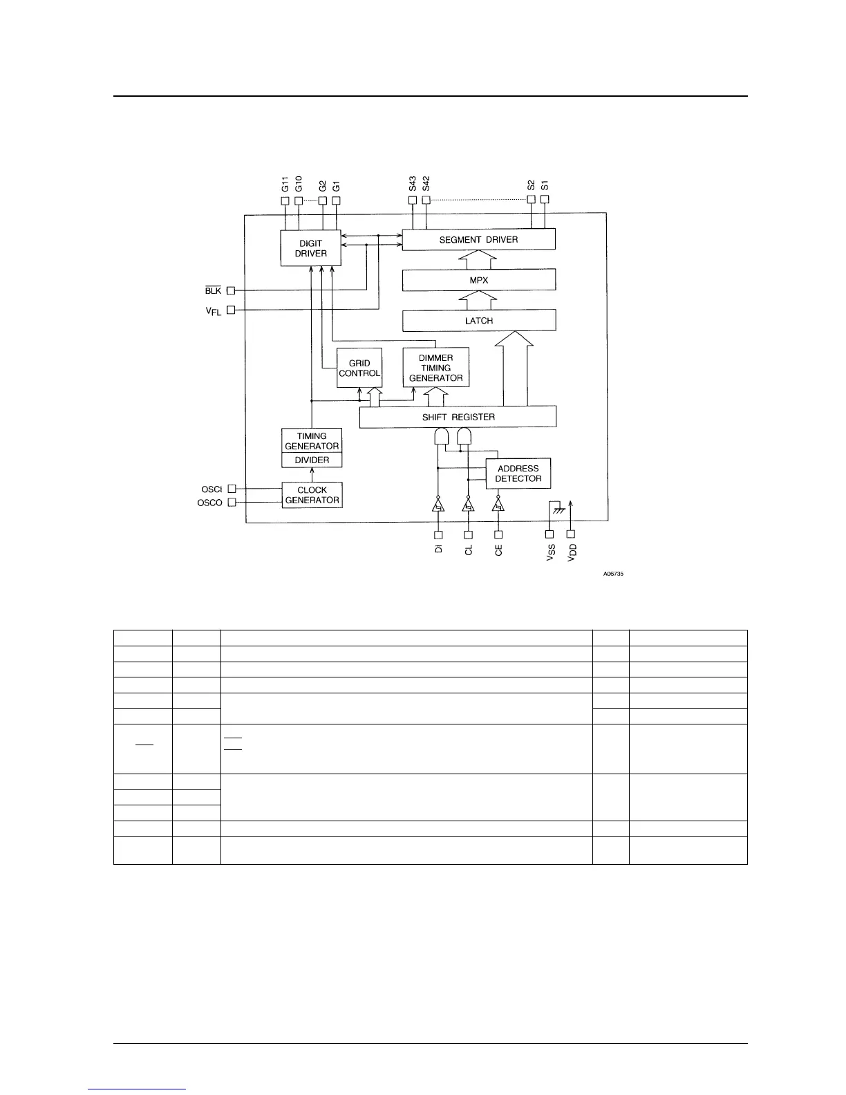
Pin Pin No. Function I/O Handling when unused
V
FL
1, 13 Driver block power supply connection. (Both pins must be connected.) — —
V
DD
60 Logic block power supply connection. Provide a voltage between 4.5 and 5.5 V. — —
V
SS
57 Power supply connection. Connect to the ground. — —
OSCI 59
Oscillator connection. An oscillator circuit is formed by connecting an external resistor
I GND
OSCO 58
and capacitor to these pins.
O OPEN
Display off control input.
BLK 61
BLK = Low (V
SS
) ... Display off. (S1 to S43 and G1 to G11 at V
FL
level.)
I GND
BLK = High (V
DD
) ... Display on.
Note that serial data can be transferred while the display is turned off.
CL 63
DI 64 I GND
CE 62
G1 to G11 2 to 12 Digit outputs. These pins are P-channel open drain outputs with pull-down resistors. O OPEN
S1 to S43 56 to 14
Segment outputs for displaying the display data transferred by serial data input. These pins
O OPEN
are P-channel open drain outputs with pull-down resistors.
Serial data transfer inputs. These pins must be connected to the system microcontroller.
CL: Synchronization clock
DI: Transfer data
CE: Chip enable

 Loading...