MITSUMI
Video Switch · 75Ω driver · Y/C mix MM1501
· Measurement Procedures (MM1505 ~ MM1508)
Consumption current ICC
Connect a DC ammeter to VCC pin and measure. Hereafter, short
the ammeter to use.
Voltage gain G
V
Input a 2.0VP
-
P(1.0VP
-
P for MM1506 and MM1508), 100kHz sine
wave to SG1. If TP1 voltage is V1 and TP3 voltage is V2, find G
V
using the following formula:
G
V = 20LOG (V2/V1) dB
Frequency characteristic fc
In the above GV measurement, if TP3 voltage at 7MHz is V3, find fc
as follows: fc = 20LOG (V3/V2) dB
Differential gain DG
Input a 2.0V
P
-
P (1.0VP
-
P for MM1506 and MM1508) staircase to SG1
and measure differential gain at TP3.
APL = 10 ~ 90%
Differential phase DP The same as for DG, but measure differential phase.
Output dynamic range V
D
Input a 100kHz sine wave to SG1. Change the amplitude of the sine
wave, and measure V
D
, the maximum amplitude under THD 1%, at TP3.
Output offset voltage VOFF Measure the DC voltage difference of each switch status at TP2.
VC1 = 2.1V and VC2 = 0.7V. Input a 2.0V
P
-
P, 4.43MHz sine wave to
SG1, and operate SW3. IF TP3 voltage when there is an output
signal on the OUT pin is V4, and when there is no signal TP3
voltage is V5, then find C
T by the following formula:
C
T = 20LOG (V5/V4) dB
Impress an optional DC voltage on TP6 and TP7. Gradually
increase from VC1 = 0V. When TP7 voltage is output on TP2, TP5
voltage is V
IH. Gradually lower from VC1 = VCC, and when TP6
voltage is output on TP2, TP5 voltage is V
IL.
SW input voltage VI
Cross talk CT
MITSUMI
Video Switch · 75Ω driver · Y/C mix MM1501
MM1511 ~ MM1512
· Switch Status
Item Symbol
Switch status
S1 S2
Consumption current I
CC 22
Voltage gain G
V
12
21
Frequency characteristic
fc
12
21
Item Symbol
Switch status
S1 S2
Differential gain DG 3 1
Differential phase DP 3 1
Y output dynamic range V
DY 21
C output dynamic range V
DC 31
· Measurement Procedures
Consumption current ICC1
Connect a DC ammeter to the VCC pin and measure. Hereafter,
short the ammeter to use.
Voltage gain G
V
Input a 2.0V
P
-
P
(1.0V
P
-
P
for MM1512), 100kHz sine wave to SG1. If TP1
voltage is V1 and TP2 voltage is V2, find G
V
by the following formula:
GV = 20LOG (V2/V1) dB
Frequency characteristic fc
In the above G
V measurement, if TP2 voltage at 10MHz (7MHz for
MM1512) is V3, find fc by the following formula.
fc = 20LOG (V3/V2) dB
Differential gain DG
Input a 2.0V
P
-
P
(1.0V
P
-
P
for MM1512)
to SG1, input a chroma signal
to SG2, and measure differential gain at TP2.
APL = 10 ~ 90%
Differential phase DP The same as for DG, but measure differential phase.
Y output dynamic range V
DY
Input a 100kHz sine wave to SG1. Measure VDY, the maximum
amplitude under THD 1%, at TP2.
Input an APL 50% luminance signal to SG1 and input a chroma
signal to SG2. Change the chroma signal amplitude and measure
V
DC, the maximum amplitude where there is no waveform
distortion at TP2.
C output dynamic range VDC
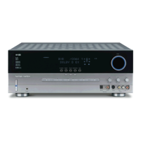
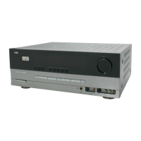
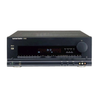
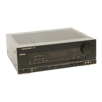
AVR325 harman/kardon
 Loading...