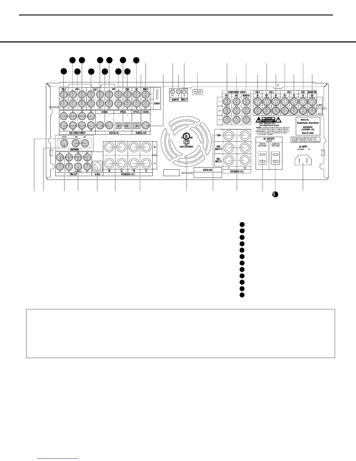
¡ AM Antenna
™ FM Antenna
£ Preamp Outputs
¢ Subwoofer Output
∞ A-BUS Connector
§ Surround Speaker Outputs
¶ Front Speaker Outputs
• Fan Vents
ª Center Speaker Outputs
‚ Surround Back/Multiroom Speaker Outputs
⁄ Switched AC Accessory Outlet
¤ Unswitched AC Accessory Outlet
‹ AC Power Cord Jack
› Video Monitor Outputs
fi DVD Video Inputs
fl Video 1 Video Inputs
‡ Video 1 Video Outputs
° Video 2 Video Inputs
· Video 2 Video Outputs
a Video 3 Video Inputs
b Component Video Monitor Outputs
c DVD Component Video Inputs
d Video 2 Component Video Inputs
e RS-232 Port
f Multiroom IR Input
g Remote IR Input
h Remote IR Output
i Coaxial Digital Audio Output
j Multiroom Audio Outputs
k Optical Digital Audio Output
CD Audio Inputs
DVD Audio Inputs
Optical Digital Audio Inputs
Tape Inputs
Tape Outputs
Coaxial Digital Audio Inputs
Video 1 Audio Inputs
Video 1 Audio Outputs
Video 2 Audio Inputs
8-Channel Direct Inputs
Video 2 Audio Outputs
Video 3 Audio Inputs
¡ AMAntenna: Connect the AM loop antenna sup-
plied with the receiver to these terminals. If an external
AM antenna is used, make connections to the
AM and
GND terminals in accordance with the instructions sup-
plied with the antenna.
™ FM Antenna: Connect the supplied indoor (or an
optional external) FM antenna to this terminal.
£ Preamp Outputs: Connect these jacks to an
optional, external power amplifier for applications
where higher power is desired.
¢ Subwoofer Output: Connect this jack to the line-
level input of a powered subwoofer. If an external sub-
woofer amplifier is used, connect this jack to the sub-
woofer amplifier input.
∞ A-BUS Connector:
Connect this jack to an optional
A-BUS-certified remote room keypad or amplifier to
extend the multiroom capabilities of your AVR 325.
See page 34 for more information on A-BUS.
§ Surround Speaker Outputs: Connect these out-
puts to the matching + and – terminals on your sur-
round channel speakers. In conformance with the new
CEA color-code specification, the blue terminal is the
NOTE:To assist in making the correct connections for
multichannel input, output and speaker connections,
all connection jacks and terminals are color-coded
in conformance with the latest CEA standards as
follows:
Front Left: White
Front Right: Red
Center: Green
Surround Left: Blue
Surround Right: Gray
Surround Back Left: Brown
Surround Back Right: Tan
Subwoofer: Purple
Digital Audio: Orange
Composite Video: Yellow
Component Video “Y”: Green
Component Video “Pr”: Red
Component Video “Pb”: Blue
REAR-PANEL CONNECTIONS
8
 Loading...