8
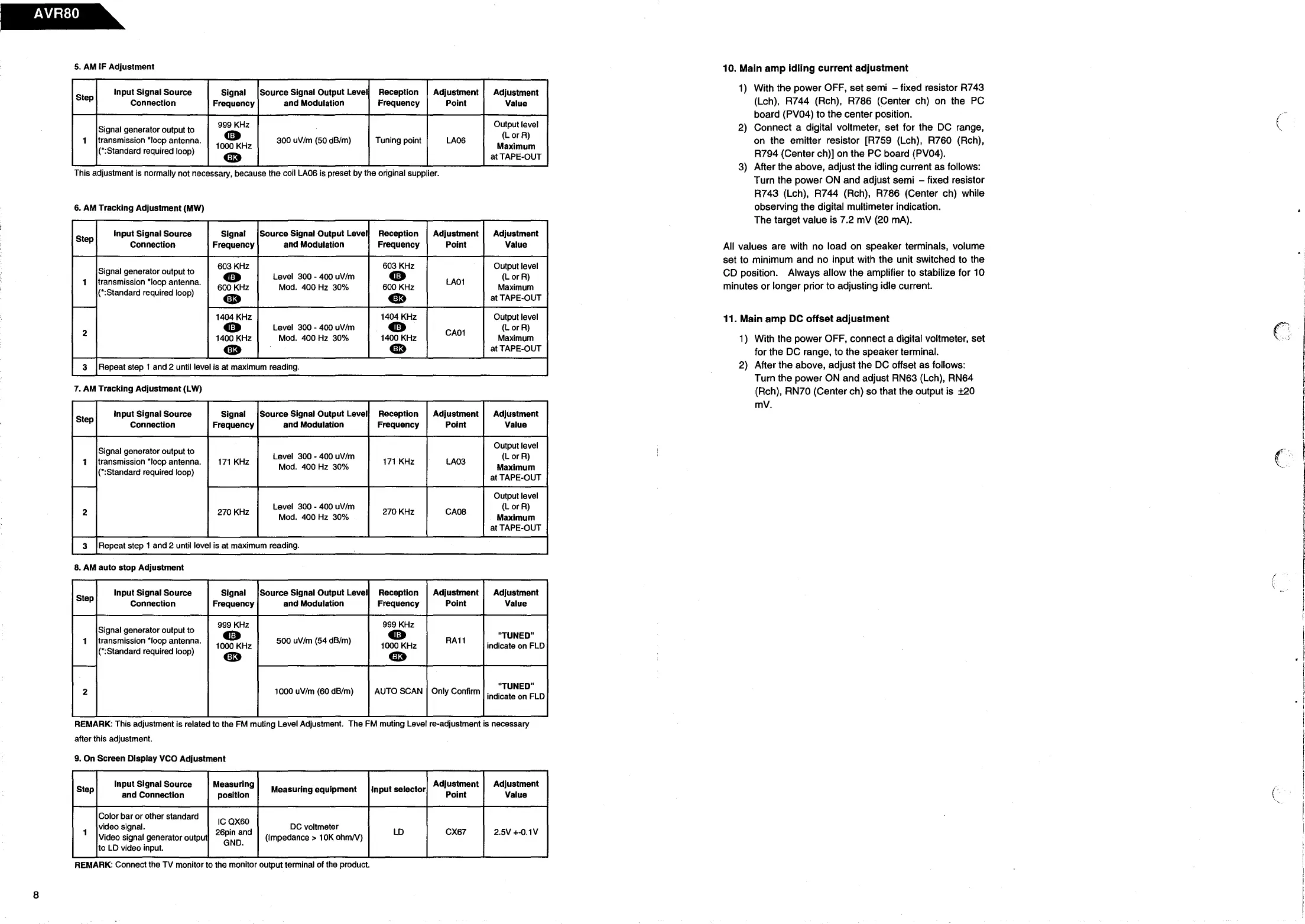
5.
AM IF
Adjustment
Step
Input Signal Source
Signal
Source Signal Output Level Reception Adjustment
Adjustment
Connection
Frequency
and Modulation Frequency
Point Value
Signal generator output to
999 KHz
Output level
1
transmission *loop antenna.
•
300 uV/m (50 dB/m) Tuning point
LA06
(LorR)
(*:Standard required loop)
1000 KHz
Maximum
•
atTAPE-OUT
This adjustment is normally not necessary, because the coil LA06 is preset by the original supplier.
6. AM Tracking Adjustment (MW)
Step
Input Signal Source
Signal
Source Signal Output Level
Reception
Adjustment Adjustment
Connection
Frequency
and Modulation Frequency
Point Value
Signal generator output to
603 KHz 603 KHz Output level
•
Level 300 - 400 uV/m
•
(LorR)
1
transmission *loop antenna.
600 KHz Mod. 400 Hz 30%
600 KHz
LA01
Maximum
(*:Standard required loop)
•
•
at TAPE-OUT
-
1404 KHz
1404 KHz
Output level
2
•
Level 300 - 400 uV/m
•
CA01
(LorR)
1400 KHz
Mod. 400 Hz 30% 1400 KHz
Maximum
•
4D
at TAPE-OUT
3
Repeat step 1 and 2 until level is at maximum reading.
7. AM Tracking Adjustment (LW)
Step
Input Signal Source Signal Source Signal Output Level
Reception Adjustment
Adjustment
Connection Frequency
and Modulation Frequency
Point Value
Signal generator output to
Output level
Level 300 - 400 uV/m
(LorR)
1
transmission *loop antenna.
171
KHz
Mod. 400 Hz 30%
171
KHz
LA03
Maximum
(*:Standard required loop)
at TAPE-OUT
-
Output level
2
270 KHz
Level 300 - 400 uV/m
270 KHz
CA08
(LorR)
Mod. 400 Hz 30%
Maximum
at TAPE-OUT
3
Repeat step 1 and 2 until level is at maximum reading.
8. AM
auto
stop
Adjustment
Step
Input Signal Source
Signal
Source Signal Output Level Reception Adjustment Adjustment
Connection
Frequency
and Modulation Frequency Point Value
Signal generator output to
999 KHz
999 KHz
•
•
"TUNED"
1
transmission *loop antenna.
1000 KHz
500 uV/m (54 dB/m)
1000 KHz
RA11
indicate
on
FLD
(*:Standard required loop)
•
•
-
2
1000 uV/m (60 dB/m) AUTO SCAN Only Confirm
"TUNED"
indicate
on
FLD
REMARK: This adjustment is related to the
FM
muting Level Adjustment. The FM muting Level re-adjustment is necessary
after this adjustment.
9. On Screen Display VCO Adjustment
Step
Input Signal Source
Measuring
Measuring equipment Input selector
Adjustment Adjustment
and Connection
position
Point Value
Color bar
or
other standard
ICQX60
1
video signal.
26pin and
DC
voltmeter
LD
CX67 2.5V +-0.1V
Video signal generator output (Impedance> 10K
ohmN)
to LD video input.
GND.
REMARK: Connect the TV monitor to the monitor output terminal of the product.
10. Main amp idling current adjustment
1)
With the power OFF, set semi - fixed resistor R743
(Leh), R744 (Reh), R786 (Center ch)
on
the
PC
board (PV04) to the center position.
2)
Connect a digital voltmeter, set for the
DC
range,
on the emitter resistor [R759 (Leh), R760 (Reh),
R794 (Center ch)]
on
the
PC
board (PV04) .
3) After the above, adjust the idling current as follows:
Turn the power
ON
and adjust semi - fixed resistor
R743 (Leh), R744 (Reh),
R786
(Center ch)
while
observing the digital multimeter indication.
The target value is 7.2
mV
(20
mA).
All
values are with
no
load
on
speaker terminals, volume
set to minimum and no input with the unit switched to the
CD
position. Always allow the amplifier to stabilize for 10
minutes or longer prior to adjusting idle current.
11. Main amp DC offset adjustment
1) With the power OFF, connect a digital voltmeter, set
for the
DC
range, to the speaker terminal.
2)
After the above, adjust the
DC
offset as follows:
Turn the power
ON
and adjust RN63 (Leh), RN64
(Reh), RN70 (Center ch) so that the output is ±20
mV.
(
. :
C
(
 Loading...