ASAHI KASEI [AK5392]
0188-E-01 1997/11
- 3 -
PIN/FUNCTION
No. Pin Name I/O Function
1 VREFL O Lch Reference Voltage Pin, 3.75V
Normally connected to GNDL with a 10uF electrolytic capacitor and
a 0.1uF ceramic capacitor
2 GNDL - Lch Reference Ground Pin, 0V
3 VCOML O Lch Common Voltage Pin, 2.5V
4 AINL+ I Lch Analog positive input Pin
5 AINL- I Lch Analog negative input Pin
6 ZCAL I Zero Calibration Control Pin
This pin controls the calibration reference signal.
"L":VCOML and VCOMR
"H":Analog Input Pins(AINL
±
,AINR
±
)
7 VD - Digital Power Supply Pin, 3.3V
8 DGND - Digital Ground Pin, 0V
9 CAL O Calibration Active Signal Pin
"H" means the offset calibration cycle is in progress. Offset calibration starts
when
RST
goes "H". CAL goes "L" after 8704 LRCK cycles.
10
RST
I Reset Pin
When "L", Digital section is powered-down. Upon returning "H", an
offset calibration cycle is started. An offset calibration cycle should always
be initiated after power-up.
11
12
SMODE2
SMODE1
I
I
Serial Interface Mode Select Pin
MSB first, 2's compliment.
SMODE2 SMODE1 MODE LRCK
L L Slave mode : MSB justified : H/L
L H Master mode : Similar to I2S : H/L
H L Slave mode : I2S : L/H
H H Master mode : I2S : L/H
13 LRCK I/O Left/Right Channel Select Clock Pin
LRCK goes "H" at SMODE2="L" and "L" at SMODE2="H" during reset
when SMODE1 "H".
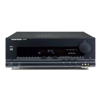
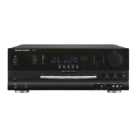
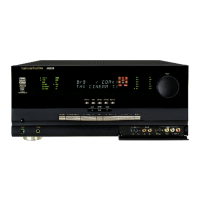
AVR8000 harman/kardon
 Loading...