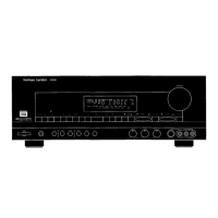
Figure 13
Front control panel (Figure 13). The connecting cables are short; take care not to break any of the
contacts or plastic housing.
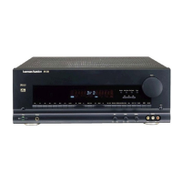
Figure 14
View of the unit with ¾ of the boards, the 3-channel amp assembly, rear panel and front control panel
removed. Figure 14 shows the transformer, filter caps, power supply board, and the 2 channel board still in
the chassis.
AVR8000
harman/kardon
 Loading...