19
3-90-08101R23_06/13
NOTE: KEEP THE FAN/LIMIT CONTROL INSTRUCTIONS
WITH THE OWNERS MANUAL FOR FUTURE REFERENCE.
NOTE: If fans are used in the fuel storage area, they
should be installed so as not to create negative pressure
in the room where the solid-fuel-burning appliance is
located.
FAN/HIGH LIMIT CONTROL
Installation & Set-up
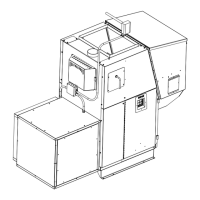
1. TheFanControlmustbeplacedinthedischargeplenum
approximately11inchesabovethedischargeopeningof
thefurnace,asclosetocenteraspossible.
Note: Thebestplaceisonthesamesideastheashdoor
becauseofeaseofaccess.SeeFig.35.
Note:CaremustbetakenwheninstallingtheFanControl
whenanairconditioningACoilisused.TheFanControl
must always be installed below theA Coil in lowplenum
installations.
2. Installtheexandwiring.
3. Makesurethattheueventingwillnotinterferewiththe
extotheFanControl.
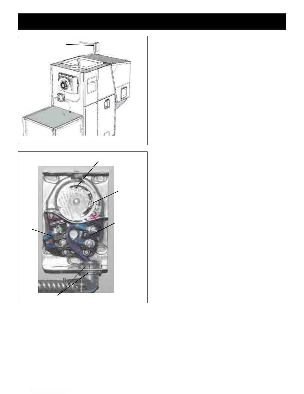
4. PryoutoneofthebottomknockoutsoftheFanControl.
Installthe90degreeexconnectorasshowninFig.36.
Oneofthelocknutsstaysontheoutsideoftheboxand
onegoesontheinsidetotightentheconnectorintoplace.
Thisallowsformaximumroomforthewiresaroundthe
switches.
5. REMOVE THE COPPER JUMPER BETWEEN THE
LIMIT AND CONTROL SWITCHES. (It is not needed.)
Figure36shownwithcopperjumperalreadyremoved.
6. Connect the two VIOLETwires to the FAN CONTROL
switch.(Itdoesn’tmatterwhichwireisonwhichscrew).
SeeFig.36.
7. ConnecttheWHITEandSKYBLUEwirestotheLIMIT
switch.(Itdoesn’tmatterwhichwireisonwhichscrew).
SeeFig.36.
8. Makesurethatallofthewiresareoutofthewaywhen
closingthecover.(Excesstwistingandpinchingofthe
wirescouldcauseashortcircuit.)
9. HIGH LIMIT setup is simple, just rotate the high limit
pointerclockwiseuntilitisagainstthetamper-proofscrew.
(Neveradjustthisscrew)
10. FANCONTROLsetup:Movebothfancontrolpointers
together until they touch, then rotate both pointers
togetheruntilthegapbetweenthemisdirectlyoverthe
middle0of100.SeeFig36.
Note:Thisis the bestfan control position wehave found
during factory testing. These fan control settings can be
adjustedifdesired.
Installation
Fig. 35
High limit fan control
Fig. 36
High Limit
Setpoint
CONTROL
Fan Control Setpoint
LIMIT
Locknuts outside and inside

 Loading...