20
3-90-08101R23_06/13
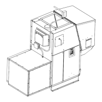
Installing Electrical Power:
Toinstallpowertothefurnacerstremovethecoveronthe
circuitbreakerjunctionboxshown.
Insideyouwillndthemainterminalblock.(Seewiringdiagram
on page 36 for location of main terminal block and proper
powerconnections).Inthebottomoftheboxaknockouthole
isprovidedfortheincomingwire.
The minimum recommendedcircuitis15Amp120V.A.C.60
Hz.Thisfurnaceshouldbetheonlyapplianceonthecircuit.
This furnace should never be powered by the use of an
extension cord.
Therecommendedhighandlowvoltagesare,130V.A.C.60
Hzmaximumhighvoltage,and113V.A.C.60Hzminimum
lowvoltage.
The furnace will continueto operate at voltages as low as
105V.A.C.,althoughitcannotbeguaranteedthatautomatic
ignitionwilloccur.Also,thereisthepossibilityofadistribution
blowermotoroverload.
NOTE: If other sources of electrical power are to be
used (such as a generator) for normal operation or
emergency operation, this source should be checked
before installation. Many generators and inverters may not
supply 120V.A.C. 60Hz. power stable enough to operate
the control board properly. (Control board damage could
occur).
Checking & Recording the Low Draft:
Aftertheventingiscompleted,thereboxlowdraftwillneed
tobecheckedandpossiblyadjusted.Afterremovingthe3/8”
boltfromthedraftholeshowninFig.38,insertthedraftmeter
tube.Theinnerashdoorandthehopperlidmustbelatched
duringthistest.(Itisrecommendedthatthedraftmeterhave
ascaleof0to1”WC.)
TurntheFeedAdjusterto“Test”.thiswillstartthecombustion
blower and allow you to check and record the High Draft
______-IWCdate_______(Thereisnoadjustmentfor
theHighDraft)
After the first 60 seconds, the “Test” mode lowers the
combustionblowervoltagetotheLowBurnvoltage.During
this lowered voltage cycle the Low Burn Draft must be
checked andadjustedifnecessary.Therecommendedlow
draftsettingshouldbebetween-.25&-.35IWC.Depending
ontheamountofverticalrise,itmaynotbepossibletogeta
lowdraftreadinginthisrange.Inthiscase,amaximumlow
draftof-.55isacceptable.
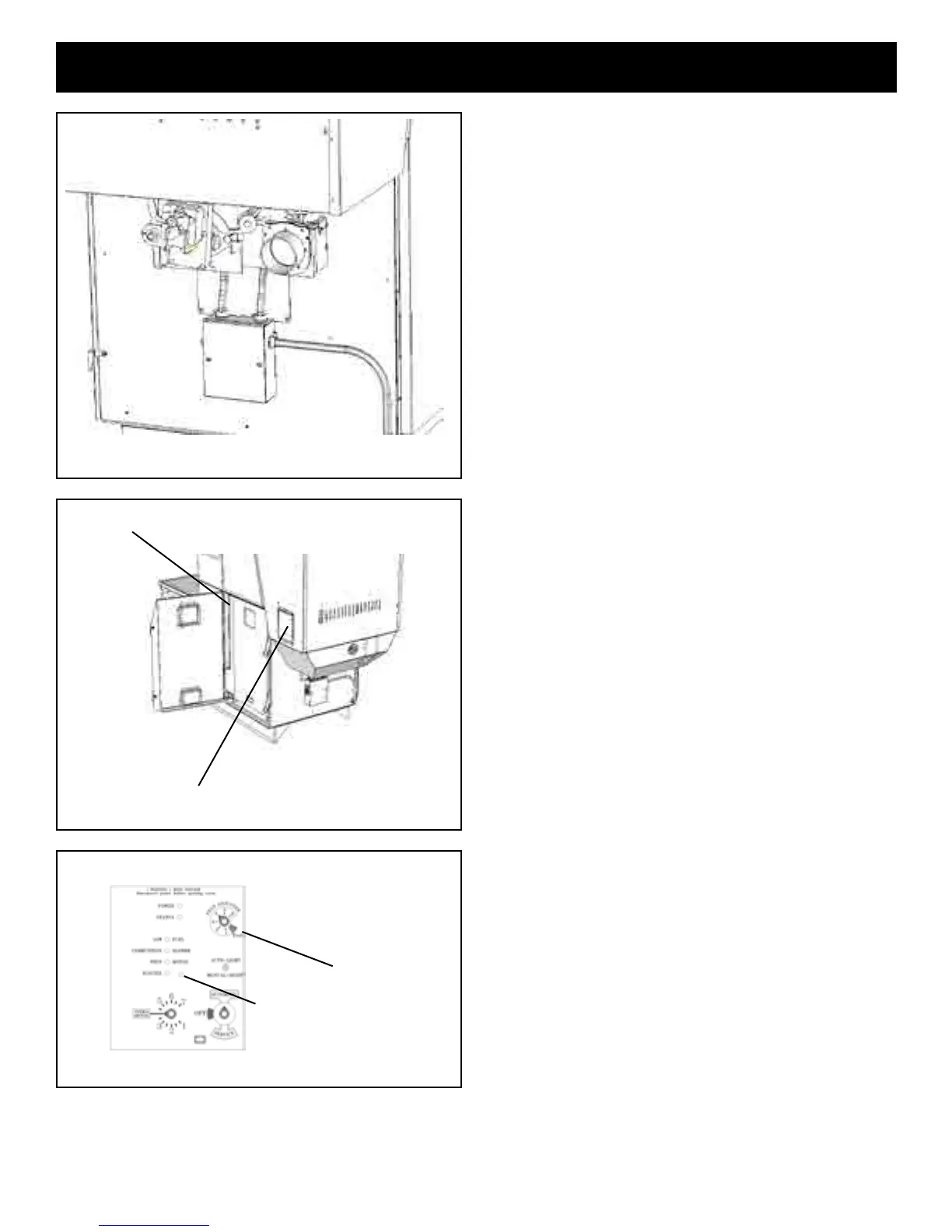
Theadjustmentscrewisthroughthesmallholetotheright
ofthe Igniter Light. See Fig. 39.Adjusted the Low Draft to
__________-IWC.
Don’t forget to turn off of “Test” mode.
Installation
Fig. 38
Draft meter bolt
Furnace Control
“Test”
Low Draft Adjustment Pot
Fig.39
Fig. 37

 Loading...