D-G 16 S2 - 18.04.13 / Vers.: 1
13
22
26
24
21
23
20
27
28
19
62
63
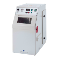
Diameter greater than
4.5 mm = exchange jet nozzle
Fig. 6: Dismantling of the injector (20) for automatic blasting
19
Injector mounting 24
Injector ring
20
Injector housing 26
Abrasive aspiration hose
21
Clip connector 27
Air hose
22
Jet nozzle 28
Arrow (Direction for dismantling the injec-
tor)
23
Injector pin 63
Rounded head screw
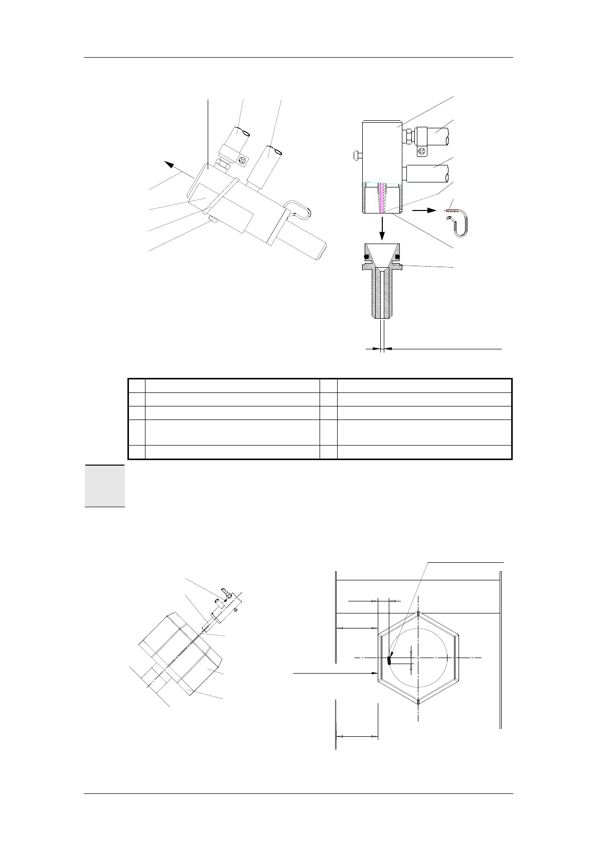
Caution
If the injector (20) is remounted for automatic blasting the injector must be aligned together with
the jet nozzle using the orientation pin (75) Correction of the orientation of the nozzle is carried
out at the two screws (15). See fig. 2 page 5 and fig. 6 page 13.
Jet nozzle
Injector
Sandblasting
cage
Back wall off
sandblasting area
Side wall of housing
Rubber plate
=
=
10
20 mm
Orientation pin
Ø 3x163 mm long
The jet nozzle and the
orientation pin must point
in this direcktion
The cage side walls
must be parallel to the
housing
Fig. 7: Orientation of the jet nozzle