Revision A • 6/06
HARRIS CORPORATION
2-16
2 Installation
mics can be set as control room talk sources, but
typically only the board operator mic, and possi-
bly a producer mic, are set to this function. Other
control room mics can talk to the studio by using
a mic control panel with a talkback button.
When STU MIC is lit, the signal is defined as a
studio mic. When the channel is turned on, the
studio monitor output mutes and the studio warn-
ing command is activated. If a mic control panel
with talkback button is used, then that mic posi-
tion can talk to the control room.
When TELCO 1 or TELCO 2 is lit, it indicates
the input signal requires a mix-minus signal from
the console. These settings are used with Telco
hybrids, ISDN connections, satellite transceivers
and other two-way devices. Only one console chan-
nel source can be set as Telco 1 and only one con-
sole channel source can be set as Telco 2.
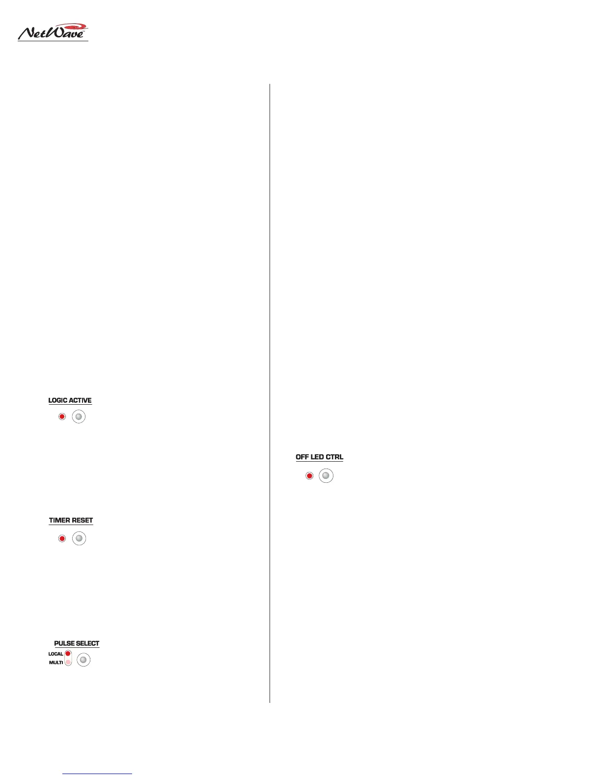
Logic Active—Sets whether the channel logic I/O
connector is active for that source.
When lit, the channel’s logic I/O
connector is active. When unlit, the
logic connector is not active for that source. Typi-
cally, only A or B is set for Logic Active on any
channel.
Timer Reset—When lit, indicates the channel strip
will send a timer reset command to
the Event Timer when it is turned
on. When unlit, no timer reset com-
mand is issued. In order for the timer reset com-
mands to reach the Event Timer, the Auto button
on the Monitor panel must be lit.
Start/Stop Pulse Generation—Affects the chan-
nel logic start and stop pulses gen-
erated for Line and Telco channel
logic. There are four conditions:
both LEDs off; Local on and Multi off; Local off
and Multi on; and both Local and Multi on.
With both LEDs off, one start or stop pulse is
generated when the channel on/off state changes
by pressing Channel On/Off or when receiving
remote logic channel on and off commands.
With the Local LED on and the Multi LED off,
a start or stop pulse is only generated when the
channel status is changed by pressing Channel On
or Channel Off. The channel can still be turned on
and off remotely, but no start or stop pulse will be
generated.
With the Multi LED on and the Local LED off,
a start pulse is generated anytime Channel On is
pressed or a start command is received. Likewise,
a stop pulse is generated anytime Channel Off is
pressed or a channel off command is received. No
channel state change is required to generate an-
other start or stop pulse.
With both the Multi and Local LEDs on, a start
pulse is generated anytime Channel On is pressed
and a stop pulse is generated each time Channel
Off is pressed. Remote channel on or off commands
do not generate any pulses.
Off Button Lighting—When unlit (the standard
setting), the Off button lights up
whenever the channel is off. When
lit, the remote logic command Ready
controls the lighting of the channel Off button.
Typically, this setting is lit for CD players and
other peripheral devices that can control a
channel’s Off button light to indicate play status.
If the peripheral is not ready (e.g., no CD loaded),
the channel off button is not lit. When the periph-
eral is ready (e.g., a CD is loaded and cued), then
the off button is lit. After the peripheral finishes
(e.g., the CD track has played) the off button winks
to indicate the event has completed.