Revision A • 6/06
HARRIS CORPORATION
2-18
2 Installation
Cabling and Wiring
All user connections are made on plug-in con-
nectors along the rear of the console. The connec-
tors are hidden in normal operation by a rear flip-
up cover that extends across the console.
To access the connectors, the cover can be com-
pletely removed by lifting it straight up when
closed, or it can be flipped open by either lifting it
from the front edge or by pressing in on the verti-
cal section at the back. The cover sits on two roll
pins that extend from the side panels. It flips open
toward the rear.
Note: The cover is typically removed
during installation to ease connector
access. To prevent scratches, set the
painted cover on a padded surface.
REQUIRED CABLES AND WIRE
The following types of wire and cable are rec-
ommended for use with NetWave consoles:
• Analog audio connections use two-conductor,
stranded, insulated, shielded cable using a
separate shield drain wire (equivalent to
Belden 8451, 9451 or 8761)
• AES/EBU connections use 110 ohm two-con-
ductor, stranded, insulated, foil-shield cable
containing a separate shield drain wire
(equivalent to Belden 1800B)
• Logic control uses stranded, 22 AWG, mul-
tiple-conductor, non-shielded, jacketed cable
(equivalent to Belden 9423, 8457 or 9421).
The number of conductors required is de-
termined by the application. Typically, cables
with five or eight wires are most often used
for constructing logic cables since, even though
there are twelve or fourteen pins on the logic
connectors, only a handful are typically con-
nected for any given application.
• Crossover CAT-5e/CAT-6 cable to connect the
VistaMax Link connector to a VistaMax frame
• Straight-thru CAT-5 cables to connect the Dual
Router kits to a VistaMax system LAN switch
WIRE PREPARATION
All NetWave audio and logic wiring terminates
in AMP MOD IV receptacle contacts. Stranded
wires of 22 to 26 AWG, with insulation diameters
of .040 to .060 inch, can be used with the MOD
IV receptacle contacts.
Follow these steps for audio wire preparation:
1 Strip the cable insulation jacket and foil shield
back 1½" [38.10 mm].
2 Remove the foil shield and sleeve the drain
wire with 20 AWG Teflon sleeving. Leave
9/64" [3.57 mm] of the drain wire exposed.
3 Cover the cut end of the jacket with 3/4"
[19.05 mm] of heat-shrink tubing. Shrink this
tubing, centered on the jacket cut end, to hold
the drain wire sleeving in place.
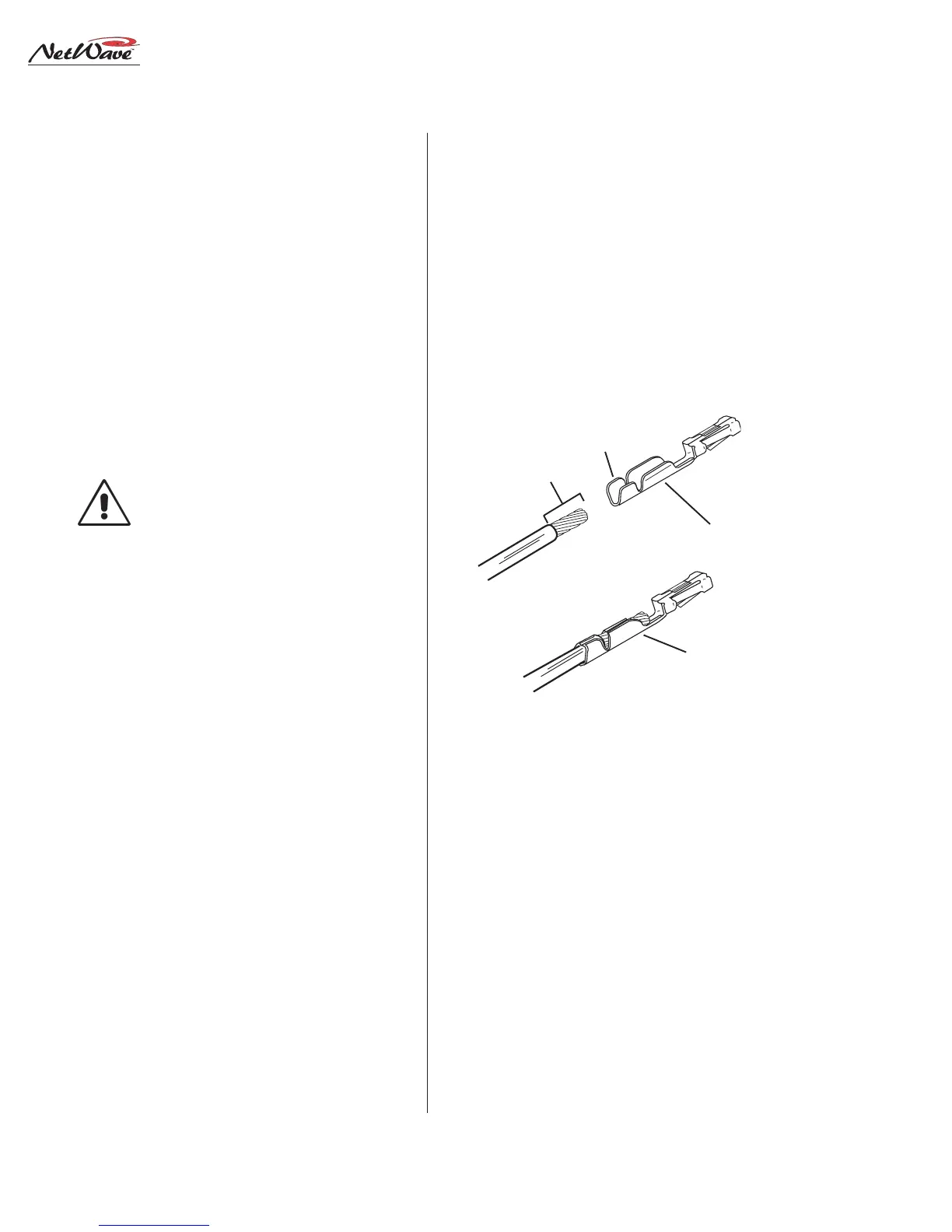
4 Strip the signal wire insulation back 9/64"
[3.57 mm].
5 Crimp the receptacle contact onto the wire
and insulation.
AMP MOD IV Receptacle Contacts
9/64” [3.57 mm]
Insulation
Crimping Barrel
Properly
Crimped Contact
Wire Crimping
Barrel