Revision A • 6/06
HARRIS CORPORATION
6-3
6 Accessories
1192) for host control of the studio speakers and
host headphone levels. Three, four, five and six
button automation control panels are available to
remotely control tape machines, news actuality
servers, digital delivery systems, delay units, etc.
Headphone Distribution Amp
The 99-1215 Harris Headphone amp, originally
designed for the BMX
digital
console, can be
repurposed to not only create a headphone amp
system for the studio, but to also give studio
speaker level control to the studio host position.
The 99-1215 has six outputs (typically for one
host and five guests, but in this application for
one host, four guests and one studio monitor am-
plifier) that connect to Harris 99-1214-x head-
phone panels using CAT-5 cables.
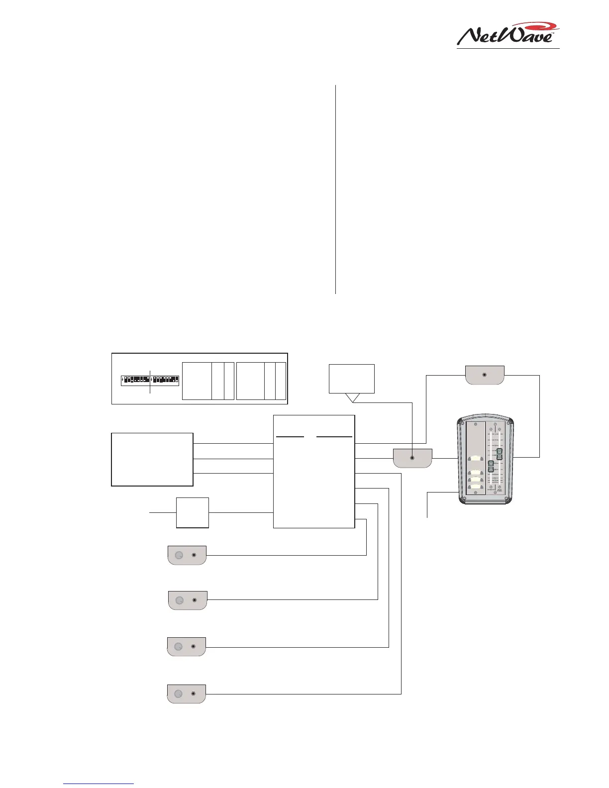
The following illustration shows how to use the
99-1215 headphone system with the NetWave. The
three inputs (Host, Co-Host and Guest) connect
to the NetWave console studio outputs: Host HP,
Monitor and Guest HP. By properly setting the
two rear panel switches (S1 and S2) per the illus-
tration, the headphone amp outputs are assigned
as: Host (#1), studio monitor (#2), and up to four
Guests (outputs #3 to #6).
USING A 99-1215 HEADPHONE AMPLIFIER WITH A NETWAVE CONSOLE,
INCLUDING USING IT FOR MONITOR SPEAKER LEVEL BY THE HOST
50-22
POWER
SUPPLY
85VAC
to 220VAC
50/60 Hz
PRE99-1215
NETWAVE
STUDIO
OUTPUTS
HOST HP
MONITOR
GUEST
HOST
CO-HOST
GUEST
POWER
INPUT
INPUTS OUTPUTS
1
2
3
4
5
6
6-PIN
MOD IV
SCREW
TERMINALS
PLUG
RJ45 CABLE
PRE99-1192
Dual Fader
Panel
PRE99-1214-3
RJ45 CABLE
PRE99-1214-3
RJ45 CABLE
PRE99-1214-3
RJ45 CABLE
GUEST 4
GUEST 3
GUEST 2
HOST
ON
OFF
COUGH
TALK
BACK
PRE99-1214-1
TO CONSOLE:
HOST'S INPUT
CHANNEL LOGIC
CONNECTOR
PRE99-1198
On/Off/Cough/
Talkback Panel
80-1788-2
Two Position
Cabinet Plate
O
N
1 2 3 4 5 6 7 8
O
N
1 2 3 4 5 6 7 8
REAR PANEL DIP SWITCH SETTINGS FOR THIS EXAMPLE
S1 S2
Off
On
Switch S1 Off On
1 - Amp 1 Source Host Guest
2 - Amp 2 Source Co-Host Guest
3 - Amp 3 Source Co-Host Guest
4 - Amp 4 Source Co-Host Guest
5 - Amp 5 Source Co-Host Guest
6 - Amp 6 Source Co-Host Guest
7 - Input Level: Host +4 dBu -8dBu
8 - Input Level: Co-Host +4 dBu -8dBu
Switch S2 Off On
1 - Amp 1 Level Ctrl Fader Fixed
2 - Amp 2 Level Ctrl Fader Fixed
3 - Amp 3 Level Ctrl Fader Fixed
4 - Amp 4 Level Ctrl Fader Fixed
5 - Amp 5 Level Ctrl Fader Fixed
6 - Amp 6 Level Ctrl Fader Fixed
7 - Guest Offset “A” 0 dBu 16dBu
8 - Guest Offset “B” 0 dBu 8 dBu
(24 dB Offset with both A & B set on)
1 2 3 4 5 6 7 8
1 2 3 4 5 6 7 8
H/P
FADER
WIRING
(11")
DC CABLE
PRE99-1214-1
(note 1)
PRE99-1214-3
RJ45 CABLE
GUEST 1
MONITOR
FADER
WIRING
(42")
FROM
MIC PANEL
NOTES:
1. Mount this panel below the countertop, or inside the
studio cabinet rack space holding the power amp, mic
processors, headphone amp, etc. The 42" long host
Monitor Fader wiring plugs into this panel.
2. Make a 1/4" TRS adapter cable (tip is the left channel,
ring is the right channel) to go from the 99-1214-1 jack to
the studio monitor power amp. For most applications, the
unbalanced signals easily drive balanced amp inputs. If in
doubt, use an unbalanced to balanced line adapter.
3. To set the monitor output levels on an amplifier with
trim or level controls: adjust the amp controls to full off. Set
the Monitor fader on the studio panel to 0 (full on). Set the
console Studio Monitor pot to maximum. Assign a signal to
the Studio Monitor output, then adjust the amplifier controls
for the desired loudest level. If the signal into the amp is too
hot, adjust the console Studio Monitor pot down until the
signal is not being overdriven and leave it in this position.
Use the Monitor fader in the studio to adjust the speaker
volume as required. The console logic mutes the monitor
audio whenever any studio microphone is on. The output
dims when the console talks to the studio. Talk is routed to
both the studio speakers and to the host headphones. The
guest headphones do not receive talk.
STUDIO
MONITOR
POWER AMP
TRS ADAPTER
CABLE
(note 2)
L R
RJ45 CABLE
HOST
POSITION