Revision A • 6/06
HARRIS CORPORATION
6-4
6 Accessories
The Dual Fader panel (99-1192), used to con-
trol both the host’s headphone level and the stu-
dio monitors level, can mount in a Studio Control
Turret or in a Harris cabinet plate. When the Net-
Wave is part of a VistaMax system, a Two-Posi-
tion cable plate (80-1788-2) can be used to also
hold a 99-1376 VistaMax Source Selector so the
host can also select the monitor source for the stu-
dio.
The studio monitor amplifier connects using a
99-1214-1 headphone panel TRS jack. The out-
put level is controlled by the Monitor fader on the
Dual Fader panel.
The guests plug their headphones into the 99-
1214-3 headphone panels which have a volume
pot on the panel next to the TRS jack.
ESE/SMPTE Master Clock
As shipped from the factory, the NetWave clock
is autonomous, running off an internal timebase.
The clock can be synchronized to an ESE or
SMPTE master timecode signal. To do this requires
that the console display be removed from the chas-
sis so that a facility-supplied ESE or SMPTE time-
code cable can be plugged into J4 on the Clock-
Timer board.
In addition, DS1 switch settings must be set to
activate the timecode input. To use ESE timecode,
DS1-2 must be set to On. Either TC-89 or TC-90
timecode can be used. The clock autodetects which
version is being received.
If SMPTE timecode is used, set DS1-5 to on
and make sure DS1-2 is set to off. If both DS1-2
and DS1-5 are set on, then the clock is set for
SMPTE timecode.
The clock’s ESE/SMPTE signal input is bal-
anced, so either a balanced or an unbalanced sig-
nal can be used. See the above drawing for con-
nection details.
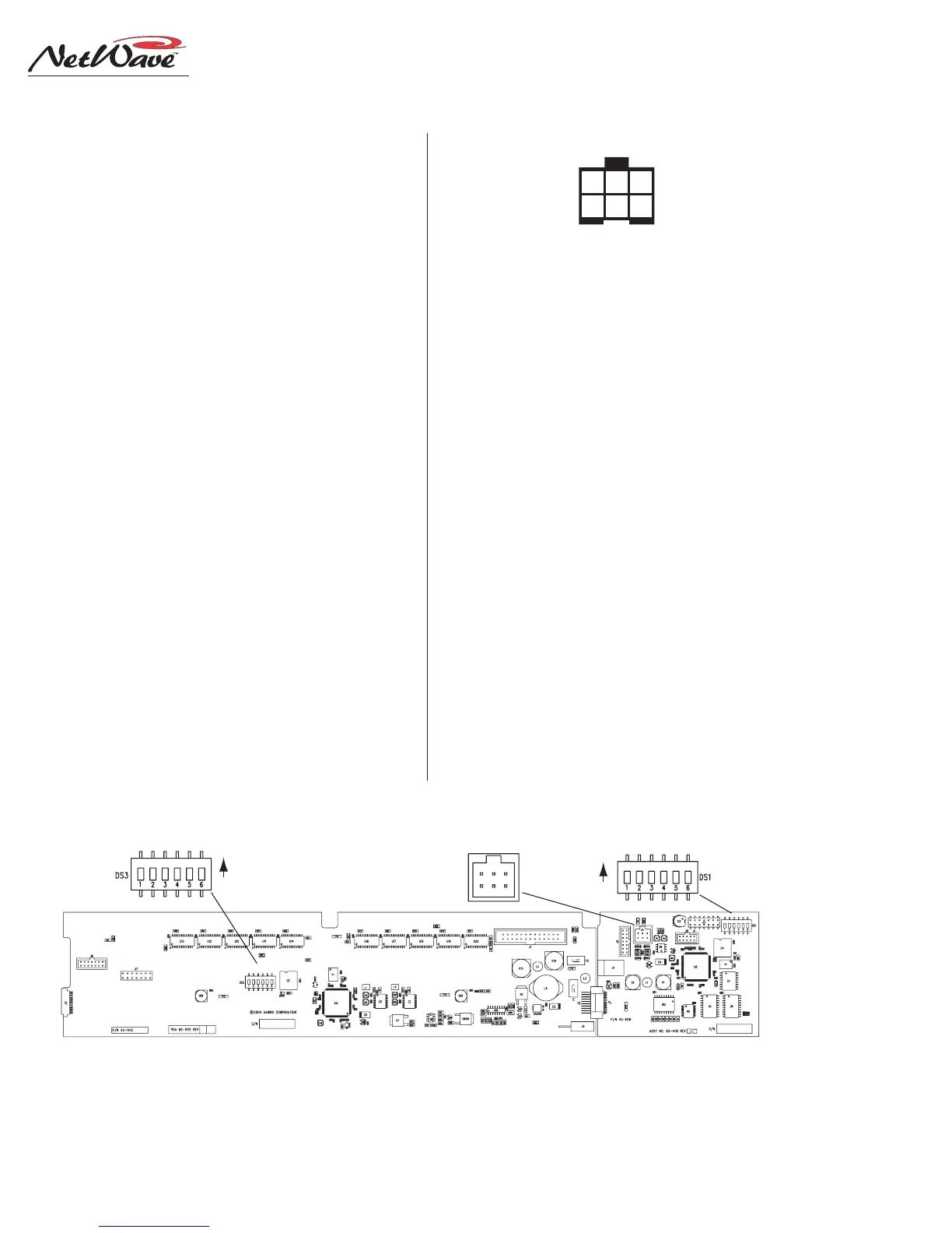
6 5 4
3 2 1
Wire insertion end view
1 - EXT. TIMER RESET INPUT
2 - GROUND
3 - TIMER RESET OUTPUT
4 - GROUND
5 - ESE/SMPTE INPUT +
6 - ESE/EMPTE INPUT -
Notes:
Pins 1 & 2. Typically not connected on a NetWave. This input resets
the timer when an active low command is received.
Pins 3 & 4. Connect to a Studio Timer's reset input. This active low
output resets the Studio Timer so it stays in sync with the console's timer.
Pins 5 & 6. Connects from a master clock. Any SMPTE, ESE TC-89 or
ESE TC-90 master clock can be used. On a balanced connection, connect
the high (+) signal to pin 5 and the low (-) to pin 6. There is no shield connection.
On an unbalanced signal, connect the center conductor to pin 5 and the
shield to pin 6.
Meter PCA Clock-Timer PCA
Meter DIP Switch, DS3 Clock-Timer DIP Switch, DS1
Clock-Timer I/O, J4
ON
ON
Console Display PCAs, showing J4, used for connecting an ESE or SMPTE master clock signal
Clock-Timer PCA connector J4 details