Revision A • 6/06
HARRIS CORPORATION
2-25
2 Installation
Microphone Logic
Microphone logic has three main functions:
mute the monitor speakers in the room with a “hot”
mic; command a hot mic warning light; and acti-
vate mic logic functions like talkback and cough.
The warning commands come from the control
room or studio logic connectors, but it is the Func-
tion parameter setting that tells the monitor logic
that the source input is a mic and where that mic
is located (control room or studio).
Mic Connections
Microphones must be preamplified to line level
before being connected to a NetWave audio input.
Typically, mics are routed through a mic proces-
sor to preamplify, equalize and compress or limit
their audio. A mic processor can connect to either
an analog or a digital input, as either can be set as
a mic input.
Mic Logic To/From a NetWave
There are two mic control panels to compliment
the NetWave console: a three-button panel with-
out talkback control (99-1197, with On, Off and
Cough buttons); and a four button panel with talk-
back (99-1198, with On, Off, Cough and Talkback
buttons). A typical mic and mic panel connection
is shown on page 2-26.
To use a mic panel, the Function parameter must
be set to CR MIC, CR MIC TLK SRC or STU MIC
to assign the source as a microphone. The Logic
Active setting must be on (the LED is lit). These
settings then allow the panel to turn the channel
on and off; to receive channel on and off tallies; to
activate the cough and talkback inputs; and to light
up the cough and talkback buttons. When the
channel is on, the room monitor output mutes,
the room warning light comes on and the On but-
ton on the mic panel and the channel are lit.
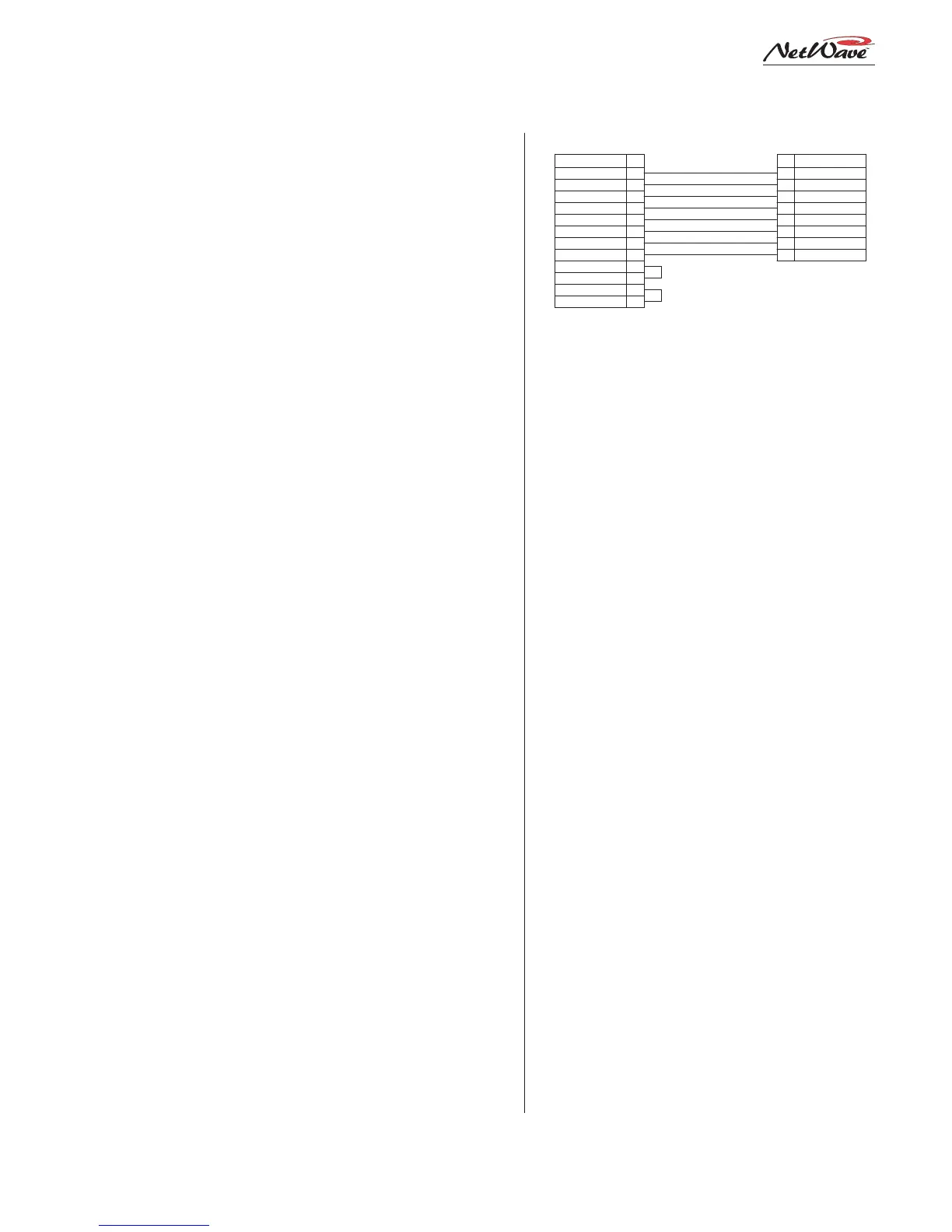
A wiring diagram for a mic panel cable (Harris
cable # 90-1875) is shown above. The panel’s
ASSIGNABLE
LOGIC CONNECTOR
99-1197 or 99-1198
MIC CONTROL PANEL
SIGNAL PIN
PIN SIGNAL
BLK
WHT
RED
GRN
BRN
BLU
ORG
YEL
Logic GND
Off Tally
On Tally
Power Supply
Off Switch
On Switch
Cough Switch
Talkback Switch
1
2
3
4
5
6
7
8
1
5
11
7
3
9
8
2
6
12
4
10
Logic Ground
Off Tally
On Tally
+5 VDC Supply
Off Switch (-)
On Switch (-)
Cough Switch (-)
Talk Switch (-)
Tally Common
+5 VDC supply
Enable Logic Inputs (+)
+5 VDC Supply
PARTS LIST
Cable: Belden 9421 or equiv.
8-pin MOD IV Housing: 14-486 (Tyco-AMP 87631-4)
12-pin MOD IV housing: 14-490 (Tyco-AMP 87922-2)
MOD IV contacts: 15-938-1 (Tyco-AMP 102128-1)
90-1875 Cable for Mic Control
switches (On, Off, Cough, Talkback) connect to the
four remote inputs on pins 2, 3, 8 and 9. Pin 4 is
jumpered to pin 10 to enable the external inputs.
The switch LEDs connect to pins 5, 7 and 11
with pin 1 supplying ground. The On Tally output
(pin 11) drives the On button LEDs and the Off
Tally (pin 5) drives the Off button LEDs. The
Cough and Talkback LEDs connect directly to +5
VDC.
To make a custom mic panel, use SPST (single
pole, single throw) momentary contact switches
with LED indicators. Tie one side of each switch
and lamp to Logic Common (pin 1). The other
side of the Cough and Talkback lamps are tied
together to +5 volts.
Each switch is tied to its logic counterpart (the
On switch goes to the On (-) input, pin 9, the Off
switch goes to Off (-) input, pin 3, etc. The on/off
lamps are tied to their Tally outputs (On lamp to
On Tally, pin 11; Off lamp to Off Tally, pin 5).
Tally Common (pin 6) is jumpered to +5 Volts
(pin 12). Pin 4, Enable Logic Inputs (+), is also
jumpered to +5 Volts on pin 10.
Line Logic
Line logic is used when the source’s Function
LEDs are all off (signifying a line input device), or
when Telco 1 or Telco 2 is lit.
When that source’s Logic Active parameter is
also lit, then the logic functions of pins 2, 5, 8 and
11 change from that of a mic logic to that required
by peripheral devices, or line logic.