Revision C • 10/07
HARRIS CORPORATION
2-5
2 Installation
the right-hand meter, which switches to display
the cue bus level while Cue is active.
The meter display mode (average only or aver-
age and peak) is set by an init.mac file setting
(which is edited using the VMCC program). The
level where the blue peak indicators turn on is set
via internal DIP switches on the meter display
boards. To change these settings, the rear/bottom
cover of the Console Display must be removed.
The 12/24-hour digital clock can be slaved to
an ESE (or SMPTE in the low profile display)
master clock. An extender cable is provided in the
display umbilical cabling for the original display
so that an ESE cable can be connected at the back
of the frame. On the reflective display, an ESE or
SMPTE cable plugs into a clock board connector.
See page 6-3 for details on master clock cabling.
The event timer is controlled manually, through
buttons on the Monitor Control panel, or auto-
matically, through channel On timer reset com-
mands.
Setting The Clock
The clock can operate in autonomous or slave
mode. When used autonomously (the factory pre-
set), a quartz crystal oscillator controls clock tim-
ing. After power is applied, set the clock manually
to the current time using a nonconductive tool
(wooden swab, toothpick, etc.) to press the recessed
time-set switches (bottom left of the original dis-
play, top right on the reflective display).
• Press Fast to increment time by minutes at
a time.
• Press Slow to increment time by seconds
at a time.
• Press and hold Hold to freeze the clock to
synch it to a time reference. Set the time
slightly ahead of the reference time. Release
Hold to start the clock.
NOTE: When slave mode is selected (see Clock
Settings), if the clock is not properly connected to
an ESE or SMPTE master clock, the clock runs
off its internal oscillator. Both display colons flash
to indicate ESE timecode is not detected.
Setting Console Display DIP Switches
To change DIP switch settings on the meters,
timer or clock requires that the rear or bottom
cover be removed to access the various printed
circuit assemblies (PCAs) in the display.
SAFETY NOTE: Even though the
switches can be changed with power
applied, for safety, turn off the console
supply (and unplug the 5-volt wall wart
on the original display) before remov-
ing the cover. Do not touch any compo-
nents on the PCAs, other than the DIP
switches, as shown in this section.
Lay the display facedown on a padded surface
(on the reflective display remove the reflector be-
fore doing this) to remove the rear/bottom cover.
On the original display the Main Meter is the up-
per right PCA, the Aux Meter is the upper left
PCA, the clock is the lower right PCA, and the
timer is the lower left PCA. On the reflective dis-
play there are only two boards: a clock-timer board
and a meter board.
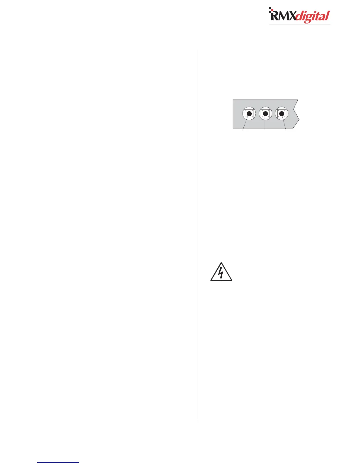
Manually Setting the Clock
Hold Slow Fast
(Reflective Display, top, right side)
Hold
Slow
Fast
(Original Display, bottom, left side)