Revision C • 10/07
HARRIS CORPORATION
2-6
2 Installation
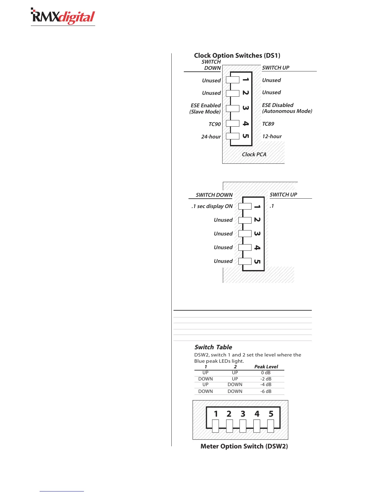
Clock Settings
The operating mode (autonomous, ESE slave
or SMPTE slave, which is only available on the
reflective display) and the clock display format (12-
or 24-hour display) are set using DIP switch DS1
on the clock PCA on the original meter and DS1
on the clock-timer PCA on the reflective meter.
For the switch settings see the illustrations for the
two displays on this and the next page.
Event Timer
The event timer displays time in minutes, sec-
onds and tenths of seconds. The only timer option
is whether the tenths of seconds digit is displayed
in Run mode. The tenths of seconds are always
shown in the Stop and Hold modes. For the switch
setting see the illustrations for the two displays
on this and the next page.
Meters
On the original display, each meter is set inde-
pendently. The Aux Meter is the left PCA, the Pro-
gram 1 Meter is the right PCA (as viewed with the
rear cover removed). On the reflective display one
set of switches set the parameters for both meters.
The switches set these parameters: the level
where the blue peak indicators turn on; whether
peak hold is active or not; and whether average
and peak or average only is displayed.
On the original display, the Program 1 Meter
has to have DSW2-5 set Down to terminate the
meter names data cable. A second DIP switch
(DSW1) assigns the meter names for each meter.
Make sure DSW1-1 is set On for the Aux Meter
and that DSW1-2 is set On for the Program 1
Meter. All other DSW1 switches must be set to
Off. For the switch settings see the illustrations for
the two displays on this and the next page.
# Switch Name DOWN Function UP Function
1 Peak Level See Switch Table See Switch Table
2 Peak Level See Switch Table See Switch Table
3 Display Mode Peak hold active No Peak hold
4unused
5 Termination Set (Main Meter) None (Aux Meter)
Meter Switch DSW2 Definitions
123456789012345678901234567890
123456789012345678901234567890
123456789012345678901234567890
123456789012345678901234567890
123456789012345678901234567890
123456789012345678901234567890
123456789012345678901234567890
123456789012345678901234567890
123456789012345678901234567890
123456789012345678901234567890
123456789012345678901234567890
123456789012345678901234567890
123456789012345678901234567890
Switch Table
DSW2, switch 1 and 2 set the level where the
Blue peak LEDs light.
12Peak Level
UP UP 0 dB
DOWN UP -2 dB
UP DOWN -4 dB
DOWN DOWN -6 dB
12 3 4 5
Meter Option Switch (DSW2)
23456789012345678901
23456789012345678901
23456789012345678901
23456789012345678901
23456789012345678901
23456789012345678901
23456789012345678901
23456789012345678901
23456789012345678901
23456789012345678901
23456789012345678901
23456789012345678901
23456789012345678901
23456789012345678901
23456789012345678901
23456789012345678901
23456789012345678901
23456789012345678901
23456789012345678901
23456789012345678901
23456789012345678901
23456789012345678901
23456789012345678901
23456789012345678901
23456789012345678901
23456789012345678901
23456789012345678901
23456789012345678901
23456789012345678901
Clock Option Switches (DS1)
12 3 45
SWITCH
DOWN
Unused
Unused
ESE Enabled
(Slave Mode)
TC90
24-hour
Clock PCA
SWITCH UP
Unused
Unused
ESE Disabled
(Autonomous Mode)
TC89
12-hour
12345678901234567890123456789
1
234567890123456789012345678
234567890123456789012345678
234567890123456789012345678
234567890123456789012345678
234567890123456789012345678
234567890123456789012345678
234567890123456789012345678
234567890123456789012345678
234567890123456789012345678
234567890123456789012345678
234567890123456789012345678
234567890123456789012345678
234567890123456789012345678
234567890123456789012345678
234567890123456789012345678
234567890123456789012345678
234567890123456789012345678
234567890123456789012345678
234567890123456789012345678
234567890123456789012345678
234567890123456789012345678
234567890123456789012345678
234567890123456789012345678
234567890123456789012345678
234567890123456789012345678
234567890123456789012345678
234567890123456789012345678
234567890123456789012345678
234567890123456789012345678
234567890123456789012345678
9
12345678901234567890123456789
12345
SWITCH DOWN
.1 sec display ON
Unused
Unused
Unused
Unused
SWITCH UP
.1 sec display
OFF
Unused
Unused
Unused
Event Timer Option Switches (DS1)