Revision C • 10/07
HARRIS CORPORATION
3-5
3 Operation
MONITOR CONTROL PANEL QUICK GUIDE,
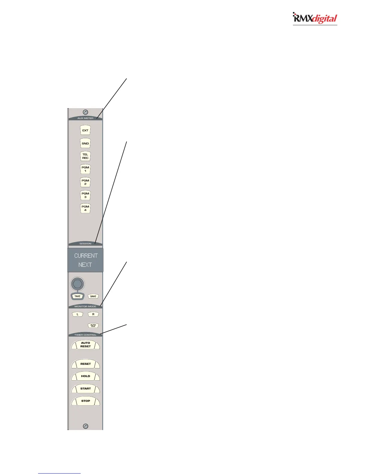
LEFT COLUMN CONTROLS
AUX METER
The buttons in this section have removable lenses for custom labels. The signal assigned to each
button is set during console configuration. As shipped from the factory, the assigned signals are:
EXEX
EXEX
EX
T — T —
T — T —
T — When lit, assigns an External input (like Real Air) to the Aux meter.
SEND — SEND —
SEND — SEND —
SEND — When lit, assigns the Send bus to the Aux meter.
TEL REC — TEL REC —
TEL REC — TEL REC —
TEL REC — When lit, assigns the Telco Record output to the Aux meter.
PGM 1-4 — PGM 1-4 —
PGM 1-4 — PGM 1-4 —
PGM 1-4 — When lit, assigns one of the four Program buses to the Aux meter.
SESSION CONTROLS
These controls allow the operator to load and save a session file.
SS
SS
S
ession Nession N
ession Nession N
ession N
ame Dame D
ame Dame D
ame D
isplaispla
isplaispla
ispla
y — y —
y — y —
y — The top line (Current) shows the name of the currently loaded
session. The bottom line (Next) shows the name of another session, as selected using the Session
Selector. The Next session is made the Current session by pressing the Take button.
SS
SS
S
ession Session S
ession Session S
ession S
elecelec
elecelec
elec
tt
tt
t
or — or —
or — or —
or — A rotary encoder to alphanumerically list the names of previously saved
session files, which appear in the bottom line of the Session Name Display.
TT
TT
T
AKE — AKE —
AKE — AKE —
AKE — Press to make the Next session active. The Current and Next names will be the same
until the Session Selector is rotated.
SASA
SASA
SA
VE — VE —
VE — VE —
VE — Press to save the Universal Dual Fader panels’ button settings, input source names and
other information as a new session saved locally in the console. The new session name is the current
session name plus a numerical suffix.
Note:Note:
Note:Note:
Note: Save always creates a new session. Operators cannot
overwrite or damage any existing session.
MONITOR MODE
L & R — L & R —
L & R — L & R —
L & R — With both buttons unlit, the CR monitor and CR headphone outputs are stereo. With only
L (left) lit, the left bus source feeds both the left and right outputs. With only R (right) lit, the right
bus source feeds both outputs. With both lit, the left and right outputs are a sum of the bus source.
AA
AA
A
UTUT
UTUT
UT
O CUE — O CUE —
O CUE — O CUE —
O CUE — When lit, allows cue to interrupt the operator headphone output following the
routing method set during console configuration. When unlit, cue does not go to the operator
headphone output.
TIMER CONTROL
This section has the controls for the event timer in the Console Display.
AA
AA
A
UTUT
UTUT
UT
O RESET — O RESET —
O RESET — O RESET —
O RESET — When lit, allows the timer to reset when a channel—with its timer reset function
enabled by the session file, is turned on. The timer resets to 00:00.0 and starts counting upward.
When unlit, the timer ignores channel timer reset commands.
RESET — RESET —
RESET — RESET —
RESET — Resets the timer to 00:00.0. The timer then counts up from 00:00.0.
HOLD — HOLD —
HOLD — HOLD —
HOLD — When pressed and held, stops the timer’s display to show the elapsed time (the timer itself
continues to run). Releasing HOLD
returns the timer display to the current run time.
STST
STST
ST
ARAR
ARAR
AR
T — T —
T — T —
T — Starts the timer from the displayed time.
STST
STST
ST
OP — OP —
OP — OP —
OP — Stops the timer with the elapsed time displayed. Press START to continue counting up
from the displayed time. Press RESET and STOP together to reset the timer to 00:00.0.