Revision C • 10/07
HARRIS CORPORATION
4-15
4 RMX
digital
Server
(from 1 to 127), called the Room Code, is as-
signed to each room. When this code is also
assigned to a mic input, when that mic is routed
to a channel strip, and the channel is turned
On, the appropriate room output mutes.
The room code entry boxes are just below
the Destination Include List entry.
Assign Real Air & Synthetic Air Sources
These two signal settings are found just be-
low the Room Mute Code settings. They are typi-
cally only set on on-air consoles that have a
several second profanity delay in the on-air sig-
nal path.
Assigning sources to these two signals tells
the control room monitor logic that it will au-
tomatically switch between the off-air signal
(called the Real Air source—used when no mic
channel is On), and a non-delayed signal (called
the Synthetic Air source—used whenever any
control room mic channel is On). The Synthetic
Air source can simply be set to the PGM 1 bus,
but more often it is the output of a backup air
processor that simulates the processed sound
of the Real Air signal.
If no source is set in the Synthetic Air selec-
tion box, then automatic signal switching does
not occur. Both Real Air and Synthetic Air de-
fault to PGM 1 if there are no selections made.
To use automatic monitor switching, Real Air
must be used as the control room monitor
source. It is the default signal assigned to the
top button on the monitor selection buttons.
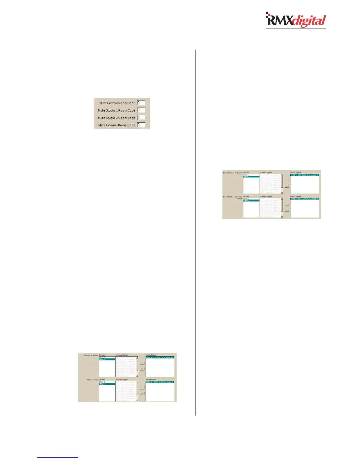
Assign Ext. Cue & Ext. Talk to CR Sources
These two signal selections—just below the
Real Air source selection box, assign two con-
sole or system inputs as the sources for an Ex-
ternal Cue input and an External Talk to Con-
trol Room input.
The External Talk signal could be from a Vis-
taMax intercom or from another switched
source. The External talk to Control Room sig-
nal is automatically routed to Phantom chan-
nel 3 to the Talk to CR bus, while the External
Cue signal is automatically routed to Phantom
channel 4 to the Cue bus. The phantom chan-
nels are controlled by the Ext. Cue and Ext.
Talk to CR logic signals on the Cue/Talk/Ext
logic connector (see page 2-22 for connection
details).
Set Operational Parameters
There are seven operational functions that are
turned on by checking each function’s Enable
box (see illustration on the next page).
When Show Meter Average is checked, the
peak display is not shown on the meters. When
Offline Signal Post Fader is checked, the chan-
nel fader affects the offline bus levels. Un-
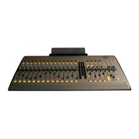
Assigning the Synthetic Air
and the Real Air Sources
Room Code Assignments
Note: the Studio 2 entry is not used in RMXdigital.
Assigning the External Cue and External
Talk to Control Room Sources