HearthStone Quality Home Heating Products, Inc. Luno Model #8160
VENTING COMPONENTS &
CONFIGURATION
Do not vent the Luno jointly with any other solid fuel or gas
appliance. Vent the Luno directly to the outside of the
building using a proper termination as listed in this manual.
The only types of venting pipe approved for use with your
Luno Direct-Vent stove is Simpson Dura-Vent’s GS,
AmeriVent Direct, Selkirk Direct Temp™ and Secure Vent
Direct-Vent Pipe. The venting configuration diagram is
shown in Figure 6. After determining the proper venting
configuration for your stove, select the vent system that will
accommodate your installation.
Caution: Ensure there is no wiring or plumbing in
the chosen location.
Caution: Do not recess venting terminations into a
wall or siding.
Note: If further direction is needed for installation, please
refer to the venting instructions, which are provided with the
venting components.
Acceptable Direct-Vent Termination Cap
Locations
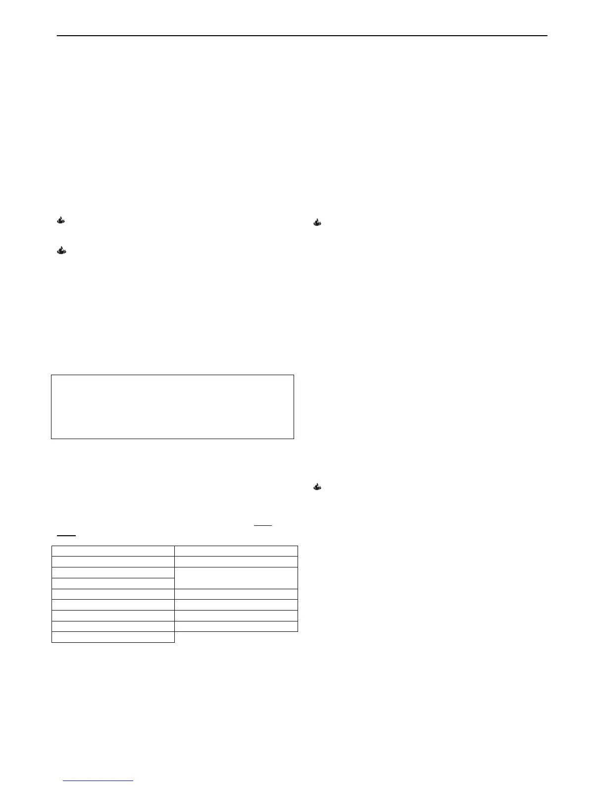
The vent/air intake termination clearances above the high
side of an angled roof are as follows:
Roof Pitch Feet Meters
Flat to 6/12 1 0.3
7/12 to 9/12 2 0.6
10/12 to 12/12 4 1.2
13/12 to 16/12 6 1.8
17/12 to 21/12 8 2.4
Listed are Simpson Dura-Vent, AmeriVent Direct, Selkirk
Direct Temp™ and Secure Vent components acceptable
for installation, along with the minimum venting kit
available. The venting system must be comprised of the
appropriate venting components as specified.
APPROVED VENTING SYSTEM COMPONENTS
(The following are components that are available, BUT
NOT necessary for all installations)
90
0
Elbow Vertical Vent Cap
45
0
Elbow Horizontal Vent Cap
6" Straight
9" Straight (Simpson only)
Vinyl Siding Standoff 4” x 6
5/8"
12" Straight Round Ceiling Support
24" Straight Thimble Covers
36" Straight Wall thimble
48" Straight 36” Snorkel
11"-14 5/8" Adjustable Pipe
CHIMNEY LINER SYSTEM
Direct-Vent Chimney Liner Termination Kit
Chimney Liner Flex
Co-Linear Flex Connector
Co-Axial to Co-Linear Appliance Connect (Masonry
approved, not to exceed 16’ measured from the stove
top)
MINIMUM VENT KIT
Vent connector (Provided with unit)
24” Straight
90 degree elbow
12” Straight
Wall Thimble Cover
Wall Thimble
Horizontal Vent Cap
Dry fit your venting and take a measurement. Pipe
dimensions will vary by manufacturer and supplier.
INSTALLATION INSTRUCTIONS FOR THE
STANDARD HORIZONTAL TERMINATION
MINIMUM VENTING KIT
1. Install the 24” straight section on top of the vent
connector.
2. Place the 90-degree elbow on the 24” section. Facing
the direction expected to penetrate the wall.
3. Attach the 12” straight section to the 90-degree elbow.
Move the stove and pipe assembly backwards until the
12” straight is flush against the wall. Pull up on the
pipe to ensure that there is a ¼” per foot rise coming
out of the stove to the wall.
4. Draw a circle around the pipe. Use the center of this
circle as the center point of the 10” x 10” square wall
pass through. Cut and frame the wall pass through
opening.
5. Place the interior wall thimble into the 10” x 10” wall
pass through. Secure it with 4 screws (not provided).
Install the exterior portion of the thimble in similar
fashion, overlapping the 2 sections.
Caution: For buildings with vinyl siding, install a
vinyl siding standoff between the vent cap and the
exterior wall.
6. Install the horizontal vent termination on the outside of
the wall. Ensure both of the retaining straps extend
through interior wall thimble. Before attaching the vent
termination to the outside of the house, run a bead of
non-hardening mastic around its’ outside edges to
ensure a good seal between it and the wall. Ensure
the arrow on the end cap points up. Secure the cap
to the wall with appropriate screws.
7. Move the stove and vent pipe into position. Make sure
the 12” vent pipe extends into the horizontal vent cap a
minimum of 1-1/4”. Secure the vent using the straps
from the horizontal vent termination to the interior 6”
pipe with 2 sheet metal screws, keeping the screws as
close to the wall thimble as possible. Bend or cut any
excess strapping, so that it is not visible after the
installation is complete.
11
 Loading...