5 | P a g e
the pipe section is depressurized during installation.
additional information provided in the instructions of the drive are observed, particularly those
referring to the adjustment of the OPEN and CLOSED positions prior to the installation of the
fitting into the pipe section.
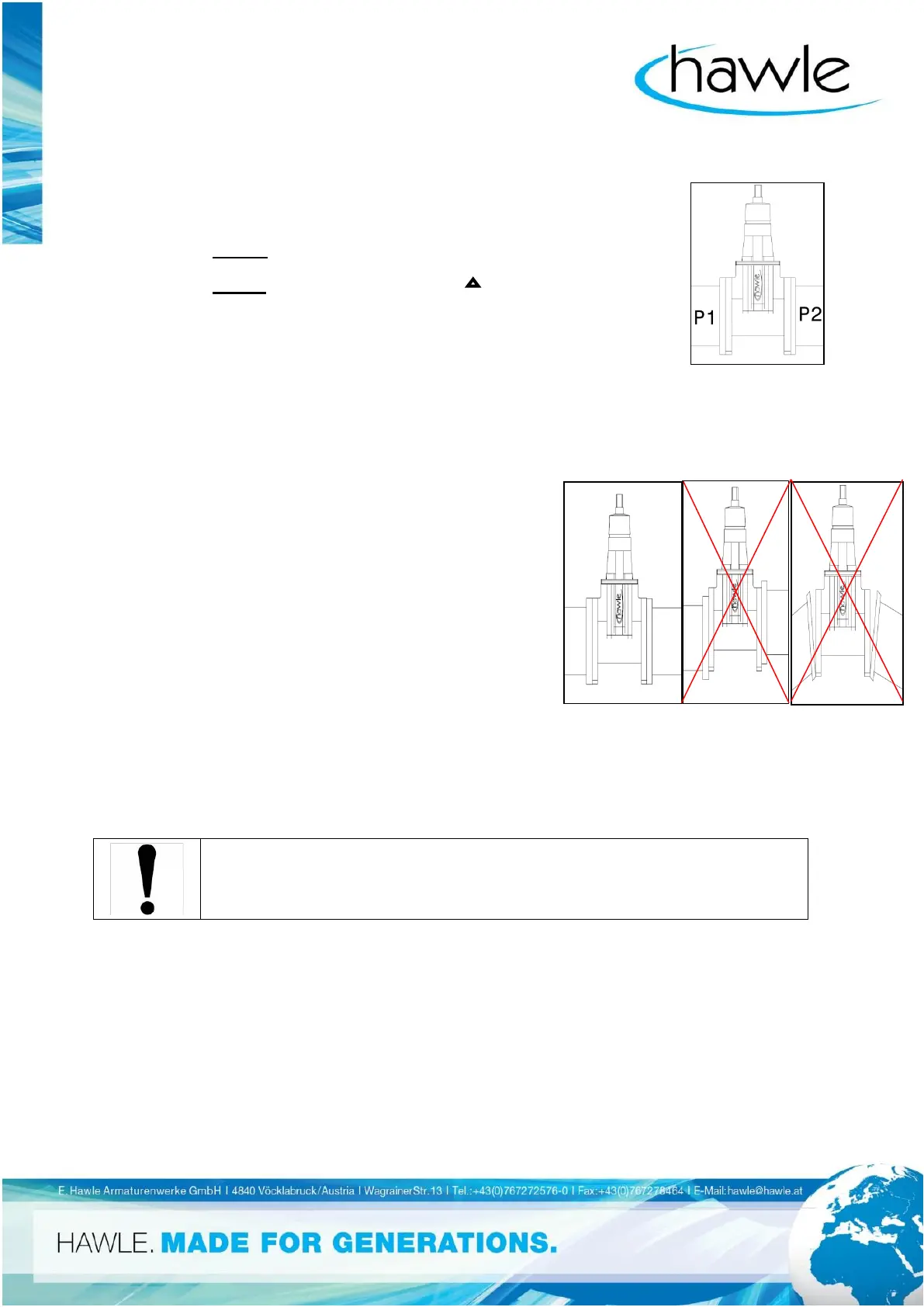
B3 Pressure, Direction of Flow and Installation Location
With the fitting opened (P1=P2), the pressure must be limited to the value
indicated as max. permissible pressure on the type plate.
With the fitting closed , the differential pressure P = (P1-P2) may not exceed the
value. (Fig. 2)
B4 Supporting the Fitting in Special Cases
The weight of the module and drive of the fitting can cause deformations and functional problems,
particularly in case of installation into oblique or vertical lines. To avoid this, the valve and drive must
then be supported on part of the building site.
If vibrations and/or pipe forces are transmitted by the pipeline, which could adversely affect the
functioning of the valve, the valve must also be supported.
Details and execution of this support are the responsibility of the user.
B5 Installation Steps
It must be ensured in accordance with Fig. 3 that
the valve and the two opposing
pipe ends are flush
and the sealing surfaces of valve and
pipeline flange are exactly parallel.
If this is not observed, the valve could be damaged through erosion
and/or dead spaces can form in front of or behind the
fitting where deposits may collect, which
could prevent tight closure of the fitting and cause corrosion
on the valve itself.
1. Insert flange seals between valve and counterflanges and center them exactly. The sealing
must cover the working strip for the flange seal fully.
2. Lightly grease the flange screws: this makes it easier to tighten and later loosen the nuts.
Use screw dimensions in accordance with HAWLE catalog sheet and depending on
used counterflanges.
3. First hand-tighten the screws all around, then tighten them evenly in a crosswise fashion (see
Fig. 4 and Catalog).
4. Consider the following tightening torques for galvanized St 4.8 steel screws (non-lubricated):