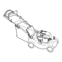
Figure29
1.Upperbeltcover
7.Removethescrewsfromtheloweranchorbracket
(Figure30).
Figure30
1.Loweranchorbracket2.Notches
Note:ThelowerbelthasbeenremovedinFigure30
forthepurposeforclarity.Itisnotnecessary
toremovethelowerbeltcovertoperformthis
procedure.
8.Movetheloweranchorbracketuponehole
(Figure30).
9.Repeatsteps1through3toadjustthecontrolbar.
Note:Whenyouinstallanewbelt,movethelower
anchorbrackettoitsoriginalfactoryposition,which
isindicatedbythenotchesnexttotheholesinthe
bracket(Figure30).
ServicingtheWheels
RemovingtheWheels
1.Stoptheengineandwaitforallmovingpartstostop.
2.Disconnectthewirefromthesparkplug(Figure12).
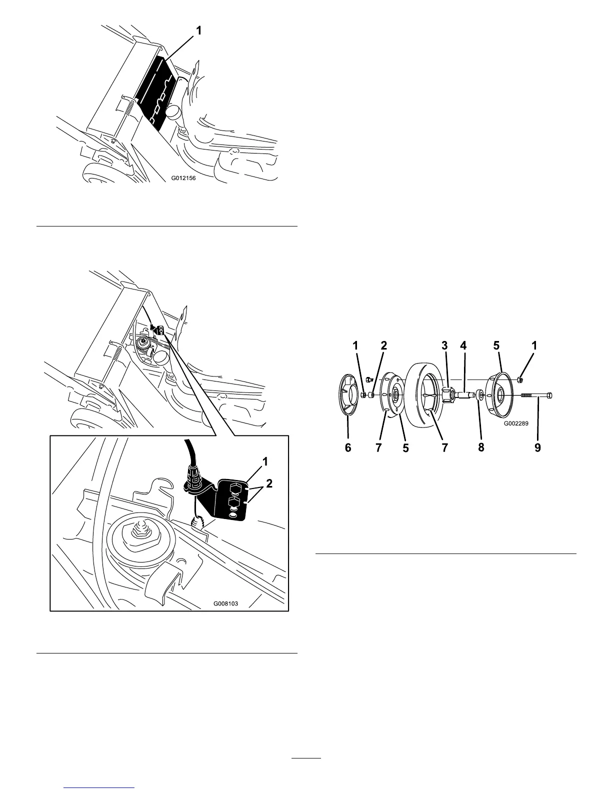
3.Removethebolt,thewheelspacer,andthelocknut
mountingthewheeltothepivotarm(Figure31).
4.Separatethewheelhalvesfromthetyrebyremoving
4capscrewsand4locknuts(Figure31).
Note:Ifyouremovethebearingsfromthe
bearing/hubassembly,removethembypressingon
thebearingspacer(Figure31).
Figure31
1.Locknuts
6.Plasticcover(rearwheels
only)
2.Wheelspacer7.Lug
3.Bearing/hubassembly8.Bearing(2)
4.Bearingspacer9.Bolt
5.Wheelhalf
AssemblingtheWheels
1.Positionthetyreontoonewheelhalf,aligningthe
lugsoneach(Figure31).
2.Placethebearing/hubassemblyintothecenterhole
ofthewheelhalf.Ensurethatthelegsofthehubare
positionedovertheangeofthehole(Figure31).
3.Placetheotherwheelhalfontothebearing/hub
assembly,aligningthewheelandthetyrelugsand
themountingholes(Figure31).
4.Using2fullythreadedscrewsorbolts(1/4-20x1.50
inch)andnon-lockingnuts,looselysecurethewheel
22