USE ONLY HAYWARD GENUINE REPLACEMENT PARTS
4
Cell
Vessel
FROM
POOL
TO
POOL
Filter
Heater
Filter
Pump
GFCI
Outlet
15 ft
ballast
cable
interlock
cable
flow
switch
cable
6 ft
9 ft
9 ft
120
VAC
Check
Valve
Bypass
NOTE: A check valve is not
necessary for salt chlorination
systems but must be installed
when using chlor ine erosion
feeders. Chlorination must take
place “downstream of the Cell
Vessel.
Inlet
3-Way
Valve
Mounting the Controller
The controller is designed to mount vertically on a flat surface with the cables facing downward. Because the enclosure also acts as a heat sink (disperses heat
from inside the box), it is important not to block the four sides of the controller. Do not mount the controller inside a panel or tightly enclosed area. If the supply
or a lamp cord is damaged, it must be replaced by the manufacturer, its service agent or similarly qualified persons in order to avoid a hazard.
After ensuring that the controller’s cables can reach their destinations, mount the controller to the intended surface using proper mounting hardware given the
size and weight of the unit. The controller’s mounting brackets require a total of 6 mounting bolts to fasten the controller to the mounting surface.
Plumbing the HydroRite System
Although not required, Hayward recommends that the HydroRite system be plumbed in a dedicated loop that can be bypassed as shown on page 3. A three-way
valve and actuator are supplied for this purpose. If plumbing a bypass, a tee fitting will be required. A bypass will aid in servicing and maintaining the HydroRite.
Note that the increased head of the HydroRite system may affect the performance of water features installed in the pool’s system. A bypass will allow you to
divert water directly to water features although be aware that the HydroRite will not sanitize under these circumstances.
Installation of 3-way valves on BOTH the inlet and outlet lines attached to the vessel plumbing is mandatory if an automatic vessel cleaner is used, or if the
vessel and associated plumbing is located below the waterline. Failure to use valves where any portion of the device is below the waterline will not allow the
device to be properly drained which could lead to cracking of the unit if any retained water freezes.
Securing the Vessel
When the vessel installation location has been determined, it should be secured to a concrete or wood base. Four mounting holes are located in the mounting
base of the unit that accommodates ¼ inch diameter bolts to mount the HydroRite unit in place. FAILURE TO PROPERLY SECURE THE UNIT MAY CAUSE NOISE
DUE TO VIBRATION CAUSED BY WATER PASSING THROUGH THE WET CHAMBER. Secure the vessel using bolts and anchors (not supplied) where necessary
and appropriate for your installation.
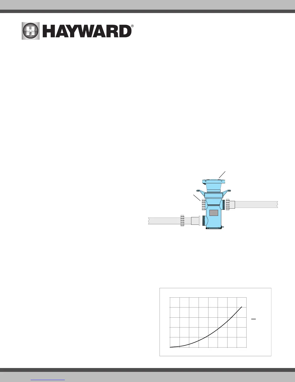
Plumbing the Vessel
The HydroRite vessel comes with union nuts and tails pre-assembled on
the housing. Remove the Inlet and Outlet nuts and note the orientation of
the orange gaskets when removing union tails. These will need to be put
back together after gluing the union tails to the pool piping.
After cutting pipe to length, slide one union nut onto the cut pipe and
glue the gray tail piece to the pipe end. Repeat for the other pipe. Thread
the union nuts onto the vessel and handtighten both unions. DO NOT
OVERTIGHTEN. OVERTIGHTENING WILL BREAK THE UNION NUTS. To avoid
stress on the connections at the vessel, piping should be supported and
should not rest solely upon the unions.
Plumbing the Flow Switch
The flow switch is a safety device that ensures that the HydroRite is only operating when there is water passing through the vessel. The flow switch must be
plumbed in the same section of plumbing as the vessel. Failure to properly install the flow switch can result in damage to the pool’s equipment.
IMPORTANT: There must be at least a 12” (30cm) straight pipe run before (upstream) the flow switch.
IMPORTANT: To ensure proper operation, verify that the arrow on the flow switch points in the direction of water flow.
Head Loss
Refer to the adjacent table below for Head Loss information.
0
5
10
15
20
25
0 10 20 30 40 50 60 70 80
Head Loss (Feet of Water)
Flow Rate (GPM)
HydroRite Head Loss
HYR2CSUV-O3
Venturi
The venturi assembly is pre-assembled and ready to be plumbed. A 3 ft
hose connection is made from the venturi to the ozone manifold at the vessel
as shown in the diagram on page 3. More information about the venturi tube
and connection can be found on page 5.
Chlorination Systems
Care must be taken to prevent exposure of the vessel to high concentra-
tions of chlorine. All in-line chlorine systems must be installed AFTER (down-
stream) the vessel.
HYD-UVO
Inlet Pipe
Union
Tail
Union
Nut
Do not
remove
Outlet Pipe
Vessel
Cap