USE ONLY HAYWARD GENUINE REPLACEMENT PARTS
3
Vessel
FROM
TO
POOL
Filter
Heater
Filter
Pump
GFCI
Outlet
15 ft
ballast
cable
interlock
cable
flow
switch
cable
6ft
9ft
9ft
120
VAC
Check
Valve
Optional Bypass
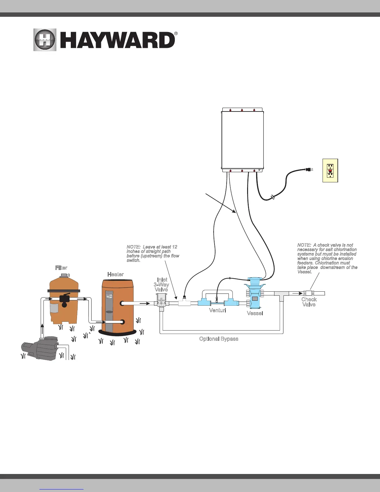
NOTE: A check valve is not
necessary for salt chlorination
systems but must be installed
when using chlorine erosion
feeders. Chlorination must
take place downstream of the
Vessel.
Inlet
3-Way
Valve
Venturi
3ft
venturi
tube
NOTE: Leave at least 12
inches of straight path
before (upstream) the flow
switch.
Cell
Vessel
FROM
POOL
TO
POOL
Filter
Heater
Filter
Pump
GFCI
Outlet
15 ft
ballast
cable
interlock
cable
flow
switch
cable
6 ft
9 ft
9 ft
120
VAC
Check
Valve
Bypass
NOTE: A check valve is not
necessary for salt chlorination
systems but must be installed
when using chlor ine erosion
feeders. Chlorination must take
place “downstream of the Cell
Vessel.
Inlet
3-Way
Valve
Installation
Before starting your installation, you MUST read this manual in its entirety in order to install your unit in a safe manner. Note that a few moments spent becoming
familiar with the HydroRite unit and its installation may save a great deal of time (and expense) later. If you have any questions that are unanswered when you
have completed the reading of this manual, contact your supplier or Hayward.
Overview
Determine a suitable location
Installation of HydroRite system requires mounting the controller and vessel, plumbing the vessel, venturi and flow switch (on the return side of the filter pump),
and finally, connecting the required cables. Remove power to the pool filter pump before starting this installation. Installation must be performed in accordance
with local and NEC code.
The HydroRite vessel must be mounted at least 10 ft. from the pool. The controller must be mounted a minimum of 6 ft. horizontal distance (or more, if local
codes require) from the pool and has a 6 ft. power cord that must be connected to a GFCI protected circuit. Refer to the diagram above for lengths of other cords
and the venturi tube. Note that the vessel and flow switch will be plumbed into the return plumbing after the heater and all other equipment with the exception
of chemical feeders and chlorination systems.
NOTE: In-line Chemical feed-
ers and chlorinators should be
plumbed AFTER the HydroRite
system