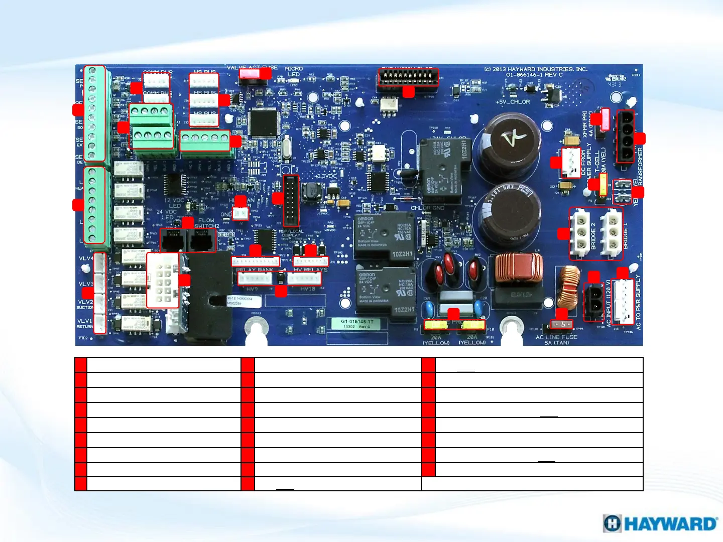
OmniLogic: Main PCB Layout (MPP)
6
A
B
C
D
E
F
G
H
I
J
K
L
M
N
O
P
Q
R
S
T
U
V
W
X
Y
Z
Blocks (SENS 1-4)
FLOW 1-2)
VAC to Power Supply
Voltage Relays (LVR 1-4)
(CHLR1)
AC to DC (Cell)
VLV 1-4)
Antenna LAN Power
Fuse (Protects Cell Circuit)
2) 4-wire Comm Bus
Bank (HVR 5-8)
Output 24VAC (Cell Circuit)
2) RS485 Comm
High Voltage Relay (HVR 1
-4)
Supply (Board Function))
3) High Speed Buses
9+10)
Fuse (Transformer + Cell Circuit)
1) High Speed Terminal Block
(2) 20A Fuse (Surge Protection)
Input 120VAC (Cell Circuit)
Fuse (Valve Actuators)
1) 5A Fuse (Prevents Overdraw)
Expansion (For I/O Expansion Card)
(Local Display)
VAC input (from Breaker)







 To Next Page