M
Megan NelsonAug 6, 2025
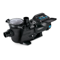
What to do if my Hayward TS540VS has maximum current exceeded?
- EErnest JohnsonAug 6, 2025
If the maximum current is exceeded in your Hayward Water Pump, the suggested solution is a drive stop.
What to do if my Hayward TS540VS has maximum current exceeded?
If the maximum current is exceeded in your Hayward Water Pump, the suggested solution is a drive stop.
What to do if my Hayward TS540VS shows an Over Temperature – Motor?
If your Hayward Water Pump's motor is overheating, the suggested solution is a drive stop special.
What to do if my Hayward Water Pump has an Internal Short Circuit Failure?
If there is an internal short circuit failure in your Hayward Water Pump, the suggested solution is a drive stop.
What to do if my Hayward TS540VS Water Pump shows Maximum temperature exceeded Power Module?
If the power module of your Hayward Water Pump exceeds the maximum temperature, the suggested solution is a drive stop special.
What to do if my Hayward TS540VS has Current Measurement Fails Permanently?
If the current measurement fails permanently in your Hayward Water Pump, the suggested solution is a drive stop.
What to do if my Hayward TS540VS Water Pump experiences an Internal Communication Failure?
If your Hayward Water Pump experiences an internal communication failure, the suggested solution is a drive stop.
What to do if my Hayward TS540VS experiences an Overload during Startup Process?
If your Hayward Water Pump experiences an overload during the startup process, the suggested solution is a drive restart.
Covers essential warnings for safe operation, installation, user capabilities, and replacement parts.
Details critical safety measures for electrical wiring, connections, pressure limits, and automatic restart.
Addresses risks associated with hazardous pressure during operation and potential component separation.
Details types of suction entrapment and measures to reduce the risk.
Covers electrical wiring safety, surge protection, bonding, and system specifications.
Guides users on how to enter the configuration menu and adjust priming time, speeds, and timers.
Provides a step-by-step guide for configuring the pump with the OmniLogic control system.
Steps for integrating the VSP with OmniLogic when plugged into a standard outside GPO.
Steps for integrating the VSP with OmniLogic via an HV Relay Controlled GPO.
Instructions for correctly priming the pump, including filling the strainer and opening valves.
Provides instructions for installing the new shaft seal, impeller, and diffuser assembly.
Details specific error codes, their descriptions, and the recommended actions for resolution.
| Brand | Hayward |
|---|---|
| Model | TS540VS |
| Category | Water Pump |
| Language | English |