Page 9
USE ONLY HAYWARD GENUINE REPLACEMENT PARTS
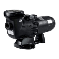
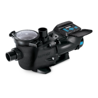
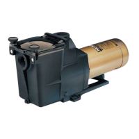
TriStar Variable Speed Pump
USE ONLY HAYWARD GENUINE REPLACEMENT PARTS
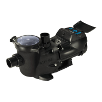
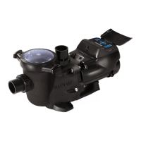
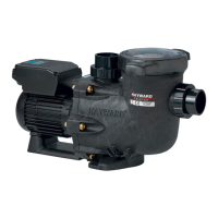
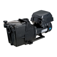
Hayward Variable Speed Pump
Page 2
Configuration Menu (Continued)
Establishing Connection with a Hayward Control System (e.g OmniLogic)
The last few screens in the Configuration Menu allow the user to alternate between “Stand Alone” Mode and RS485
Control Mode. RS485 Control Mode allows the pump to be controlled by a Hayward Control System when connected.
Firstly ensure the pump has been correctly wired to the Hayward control system. The pump must then be in RS485
Control Mode and connected to a GPO. The screens below are what will be shown whilst the pump establishes a
connection and begins communicating with the Hayward control system.
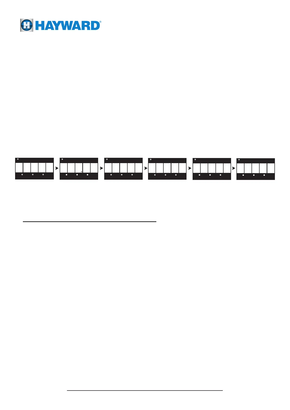
5 y4 8
This is the display for RS485 Control Mode selection.
The current display shows that RS485 Control Mode is NOT
selected and is in “Stand Alone” Mode. To leave the pump in
“Stand Alone” Mode press DISP/FUNC to exit the Configuration
Menu. Press either of the or arrow buttons to change modes.
▲ ▼
This screen shows that RS485 Control Mode has now been selected.
To save this selection, press the DISP/FUNC button.
The pump will now enter RS485 Control Mode.
When in configuration mode, the LED for the speed being configured will be constantly “FLASHING”.
When exiting configuration mode all three of the speed LED’s will “FLASH” to signify that all settings have been saved.
If the configuration mode has not been completely exited, after 2 minutes of inactivity the controller will save all of the
settings excluding the current screen settings and exit configuration mode.
Use the and arrow buttons to quickly adjust the current speed that the pump is running at. When a quick speed
change is performed the LED for the changed speed will be “FLASHING”. The LED will continue to flash until the speed
is saved, or until the timer runs out for that speed or the power is cycled to the pump.
The new speed is only saved by pressing simultaneously the and arrow buttons and then the LED for that speed
will illuminate solid.
▲
▲
▼
▼
Please Note: For full OmniLogic and RS485 connection instrustions please refer to the Communication Cable Manual
30-LITNSB019
8 5
This screen is shown
when the pump is
powering up
This second screen shows
for 3 seconds. This is the
current software revison.
The display will alternate between these two screens
if no, or until a connection with the
Hayward control system can be made.
0
1
0 0
Quick Speed Change
Saving Configuration Settings
This screen shows that a
connection has been
made with the system
but no speed input is
being sent. This will
continue until a speed
has been sent to the
pump.
Once a speed has been
sent from the OmniLogic,
the power output will be
displayed as the pump
speeds up. The screen
will alternate between
speed and power every 4
seconds.
s 4
I
l
Overview
Configuring the OmniLogic to control your variable speed pump (VSP) requires multiple steps that must be performed in
sequence. If the procedure is not followed in the proper order, the pump will not operate as intended. Typically, the
configuration of the VSP would take place during the initial configuration of the OmniLogic. Read this guide and the
Installation Manual before attempting to install your VSP.
Wiring
The OmniLogic can control the VSP whether it's plugged directly into an outside GPO or to one of the OmniLogic's HV
relay controlled GPOs. Determine which method will be used and then install the pump according to the Installation Manual.
Configuration
Configuration steps will vary depending on which wiring method is used. In both cases, the pump will have to be powered
before the OmniLogic can initiate communication. Once the VSP has been discovered and configured, the OmniLogic will
take control based on the user settings (see OmniLogic Operation Manual). Read carefully and follow the steps below
when installing the variable speed pump.
If VSP is Plugged into an Outside GPO
If powering from an outside GPO, it's best to power the VSP continuously (we recommend NOT using a timeclock).
If the VSP will not be powered continuously, ensure that it will be powered throughout the intended run time.
1. Turn on power to the VSP. If this is the first time it's been powered, the pump will start in prime mode.
If so, go to the pump and press the RUN/STOP button once to put it in Standby mode.
2. On the VSP, enter the CONFIG Menu by holding down the DISP/FUNC button until CONFIG is displayed
and then scroll through by repeatedly pressing the DISP/FUNC button until “485” is displayed.
3. Use the UP or DOWN arrow button to toggle between “y” & “n” so the display reads “485 y”.
4. Press the DISP/FUNC button to save the selection. The VSP is now in RS485 Controlled Mode and
will allow the OmniLogic to discover the HUA of the pump.
5. At the OmniLogic, enter the the Configuration Wizard (no password is needed during initial configuration).
If a password is required, use your MSP ID which can be found in System Info (see Operation Manual).
6. Advance through the Configuration Wizard. When you get to “Filter Pumps”, configure the VSP as
described in the OmniLogic Installation Manual.
7. Save and exit the Configuration Wizard.
8. You can now set a schedule for the VSP (refer to the OmniLogic Operation Manual).
USE ONLY HAYWARD GENUINE REPLACEMENT PARTS
092xxx RevA draft1
VSP Quick Start Guide
IMPORTANT: Read this guide thoroughly before installing variable speed pump.
Hayward Pool Products (Australia) Pty Ltd.
Melbourne-Sydney-Brisbane-Perth
Email: sales@hayward-pool.com.au Website: www.hayward-pool.com.au
P.O Box 4384, Dandenong South, VIC. 3164
ABN 66 083 413 414
Sales Ph 1300POOLS1 Fx 1300POOLS2
OmniLogic to VSP - HUA Access Guide