35
PME-MP55DP
HBMA0582-3.1 de/en/fr
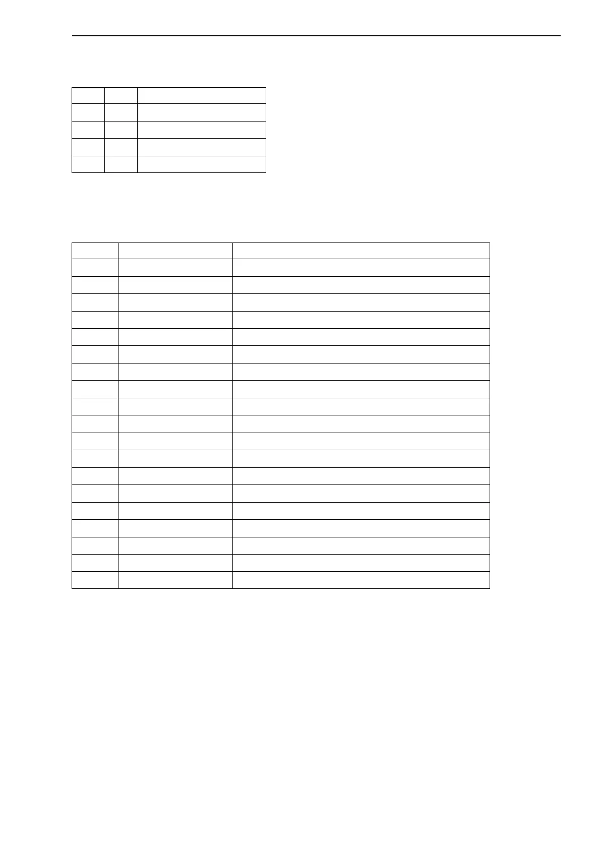
The parameter set number is coded in 2 bit binary:
Bit 8 Bit 9 Parameter set no.
0 0 1
1 0 2
0 1 3
1 1 4
Status 2
Double status word 2 returns detailed error flagging.
Bits Name Meaning
0 HardwOvfl hardware overflow
1 ADCOvfl ADC overflow
2 GrossOvfl gross signal overflow
3 NetOvfl net signal overflow
4 AOutOvfl analogue output overflow
5 MaxOvfl maximum overflow
6 MinOvfl minimum overflow
7 NegOvfl overflow in negative direction
8 GW1 status of limit switch 1
9 GW2 status of limit switch 2
10 GW3 status of limit switch 3
11 GW4 status of limit switch 4
12 SkalInError scaling input invalid
13 SkalOutError scaling output invalid
14 GainError nominal value exceeded
15 UrcalError works calibration defective
16 TransducerError transducer error
21 Stand Still standstill recognition
22−31 res reserved
Tab 6.6: Contents of status 2
6.3.2 Outputs (from the PLC to MP55IBS)
Limit values
Limit value levels are displayed in the same format as the measured values
(16 bit integer, 32 bit integer or floating format). The operating direction and
hysteresis remain unchanged and are set via the operating panel or the CAN
bus.