Page
24
( )
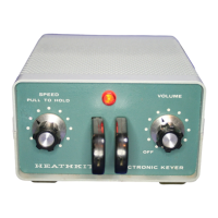
Place the slide switch in the OPR
(Op-
erate) position. The neon lamp should light.
(
)
Moving the key lever to the dot position
(right for right-hand operation) should re
-
sult in dots being heard from the speaker,
and moving the key to the dash position
(left for right-hand operation) should pro-
duce dashes. No sound should be heard
from the speaker when the lever is in the
center (neutral) position.
(
)
Turning the SPEEDcontrol clockwise should
increase the speed of the dots and dashes.
(
)
Moving the slide switch to the HOLD posi-
tion should produce a steady tone from the
speaker.
DOT-SPACE RATIO ADJVSTMENT
The following adjustment will make the dot-space
ratio equal.
The SPEED and screwdriver adjust controls
are clutch type and will track together to main-
tain the proper dot-space ratio at all settings
of the SPEED control.
If
a
VTVM
is
available, an accurate check of
the dot-space ratio can be made in the follow-
ing manner.
(
)
Set the SPEED control to the
9
o'clock
position.
(
)
Set the slide switch to the OPR position.
(
)
Turn the VOLUME control to the desired
listening level.
( )
Connect the DC test leads of the
VTVM
between the
GND
and
KEYED
LINE screws
of the 8-screw terminal board. Set the
VTVM
to
the
+15
V
DC range.
A
meter reading
of
approximately 3 volts should be obtained,
with the key lever in the center (neutral)
position.
(
)
Wold the key in the dot position. The meter
reading should be
50%
of the preflous read-
ing.
If
not, hold the SPEED control and ad-
just the screwdriver adjust control for the
proper meter reading. Place some object
against the key lever to keep it to the right
(dot position) while making this adjustment.
FINAL ASSEMBLY
Refer to Pictorial
11
for the following steps.
( )
Disconnect the power plug and position the
assemblies as shown.
(
)
Carefully position the circuit board intothe
cabinet bottom. Position the 4-wire cable
as shown. Push the line cord far enough
back through the rubber grommet so the
knot
will
fit under the circuit board.
(
)
Secure the circuit board to the cabinet,
using 6-32
x
3/8" screws into the spacers
at the power transformer end of the circuit
board. Use 6-32
x
5/8"
screws and rubber
feet into the remaining circuit board spac-
ers. The locations are indicated by the
arrows on the inset drawing
of
Pictorial
11.
This
scan
is
not
authorized
to
be
sold
on
em.
If
bought
this
scanned
manual
on
eBay,
then
the
vendor
you
bought
it
from
is
a
thief
who
sold yw
stolen
property.
Please
file
a
complaint
with
eBay
and
demand
a
refund.