Page 17
~I -----------------
START.
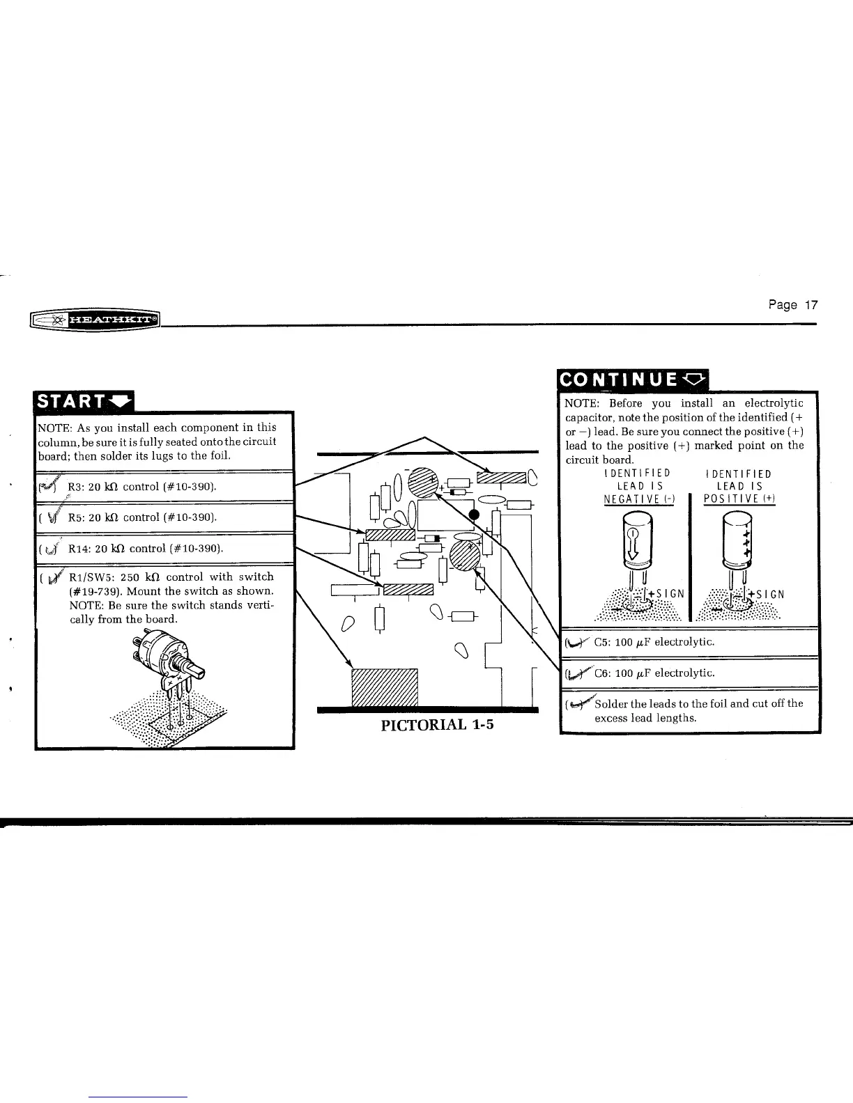
NOTE: As you install each component in this
column, be sure it is fully seated onto the circuit
board; then solder its lugs to the foil.
R1/SW5: 250 kO control with switch
(#19-739). Mount the switch as shown.
NOTE: Be sure the switch stands verti-
cally from the board .
." ,d.
'l
'f- "".
CONTIN UEQ
NOTE: Before you install an electrolytic
capacitor, note the position of the identified
(+
or -) lead, Be sure you connect the positive (
+)
lead to the positive
(+)
marked point on the
circuit board.
IDENTIFIED
LEA D IS
NEGATIVE (-)
IDENTIFIED
LEA D IS
POSITIVE
(+)
(~Solder the leads to the foil and cut off the
excess lead lengths,