Page
13
Refer
to
Pictorial 8
for
the
following
steps.
OPEN
Prepare a
10"
length
of
black solid wire.
Connect one end
of
a
10"
black wire
to
lug
11
of
switch A
(S-l).
Insert
the
other end
of
this wire
through clamps
AC
and
AD.
It
will
be
connected later.
( ) Route the red wire coming
from
circuit
board hole M
through clamps AC and
AD.
It
will
be
connected later.
( ) Connect the
yellow
wire coming
from
circuit
board
hole
E,
through clamps
AE
and
AF,
to
lug 1
of
control
T
(S-l).
( ) Connect the black wire coming
from
circuit
board
hole D, through clamps AE,
AF,
and
AG,
to
lug 2
of
switch P (S-2).
( ) Connect the green
wire
coming
from
circuit
board
hole
C,
through clamps
AE,
AF,
and
AG,
to
lug 5
of
switch P (S-2).
( ) Connect the
white
wire coming
from
circuit
board
hole B, through clamps
AE,
AF,
and
AG,
to
lug 5
of
switch N (S·2).
( ) Connect the brown
wire
coming
from
circuit
board
hole
A,
through clamps
AE,
AF,
and AG,
to
lug 8
of
switch M
(S-l).
( ) Connect the red wire coming
from
circuit
board hole
F, through clamps
AE,
AF,
and
AG,
to
lug 6
of
switch
M (S-1).
( ) Connect the
white
wire coming
from
circuit
board
hole G
to
lug 3
of
switch D
(S-l)
.
( ) Refer
to
the
inset drawing on Pictorial 8 and close
each
clamp.
To
do
this, push inward on
the
flexible
arm
until
it
locks
to
the stationary arm.
This completes the assembly and
wiring
of
the
subpanel. Set
it
aside temporarily.
FRONT PANEL ASSEMBLY AND
WI
RING
Refer
to
Pictorial 9
for
the
following
steps.
( )
Place
a
soft
cloth
on
your
work
surface
to
protect
the
front
panel
from
becoming scratched.
( ) Locate the
front
panel and position
it
as
shown.
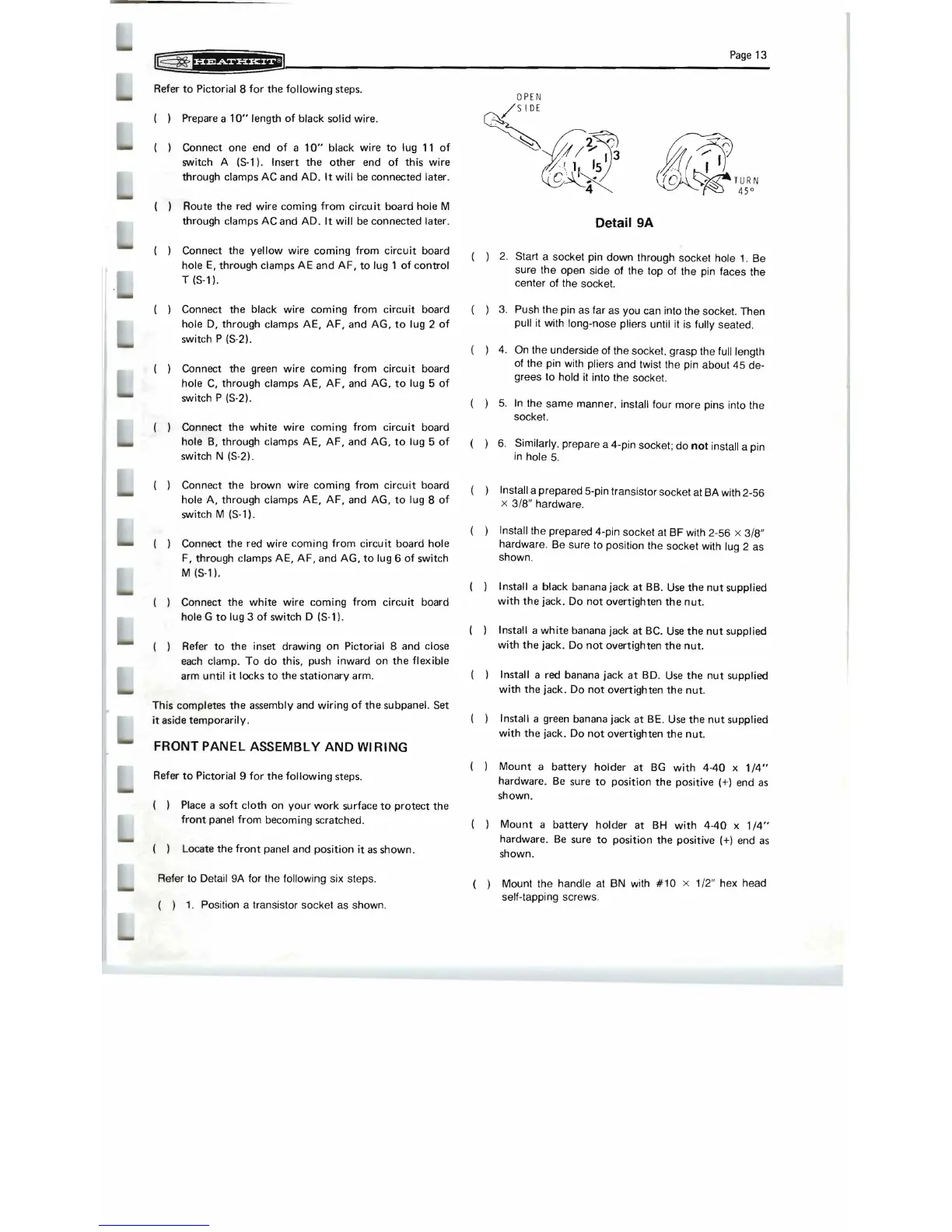
'Refer to Detail 9A for the following six steps.
( )
1.
Position a transistor socket as shown.
. / 5
IDE
. 1
3
't
/
~~
;
0'
1,
15
~~~
'
C~K
70
'~
TURN
~
45°
Detail 9A
( )
2.
Start a socket pin down through socket hole 1. Be
sure the open side of the top of the pin faces the
center of the socket.
( )
3.
Push the pin as far as you can into the socket. Then
pull it with long-nose pliers until it is fully seated.
( ) 4. On the underside of the socket. grasp the full length
of the pin with pliers and twist the pin about 45 de-
grees to hold it into the socket.
( ) 5.
In
the same manner. install four more pins into the
socket.
( ) 6. Similarly. prepare a 4-pin socket; do
not install a pin
in
hole
5.
( ) Install a prepared 5-pin transistor socket at BA with 2-56
x 3/8" hardware.
( ) Install the prepared 4-pin socket at BF with 2-56 x 3/8"
hardware. Be sure to position the socket with lug 2 as
shown.
( ) Install a black banana jack
at
BB.
Use
the
nut
supplied
with
the
jack. Do
not
overtighten
the
nut.
( ) Install a
white
banana jack at BC.
Use
the
nut
supplied
with
the
jack. Do
not
overtighten
the
nut.
( ) Install a red banana jack
at
BD.
Use
the
nut
supplied
with
the jack. Do
not
overtighten
the
nut
.
( ) Install a green banana jack at
BE
.
Use
the
nut
supplied
with
the jack. Do
not
overtighten the nut.
( )
Mount
a
battery
holder at
BG
with
4·40
x
1/4"
hardware.
Be
sure
to
position the positive (+) end
as
shown.
( )
Mount
a battery holder at
BH
with
4-40
x
1/4"
hardware.
Be
sure
to
position the positive (+) end
as
shown.
( ) Mount the handle at BN with
#10
x 1/2" hex head
self-tapping screws.
 Loading...
