Page
8
:::
o
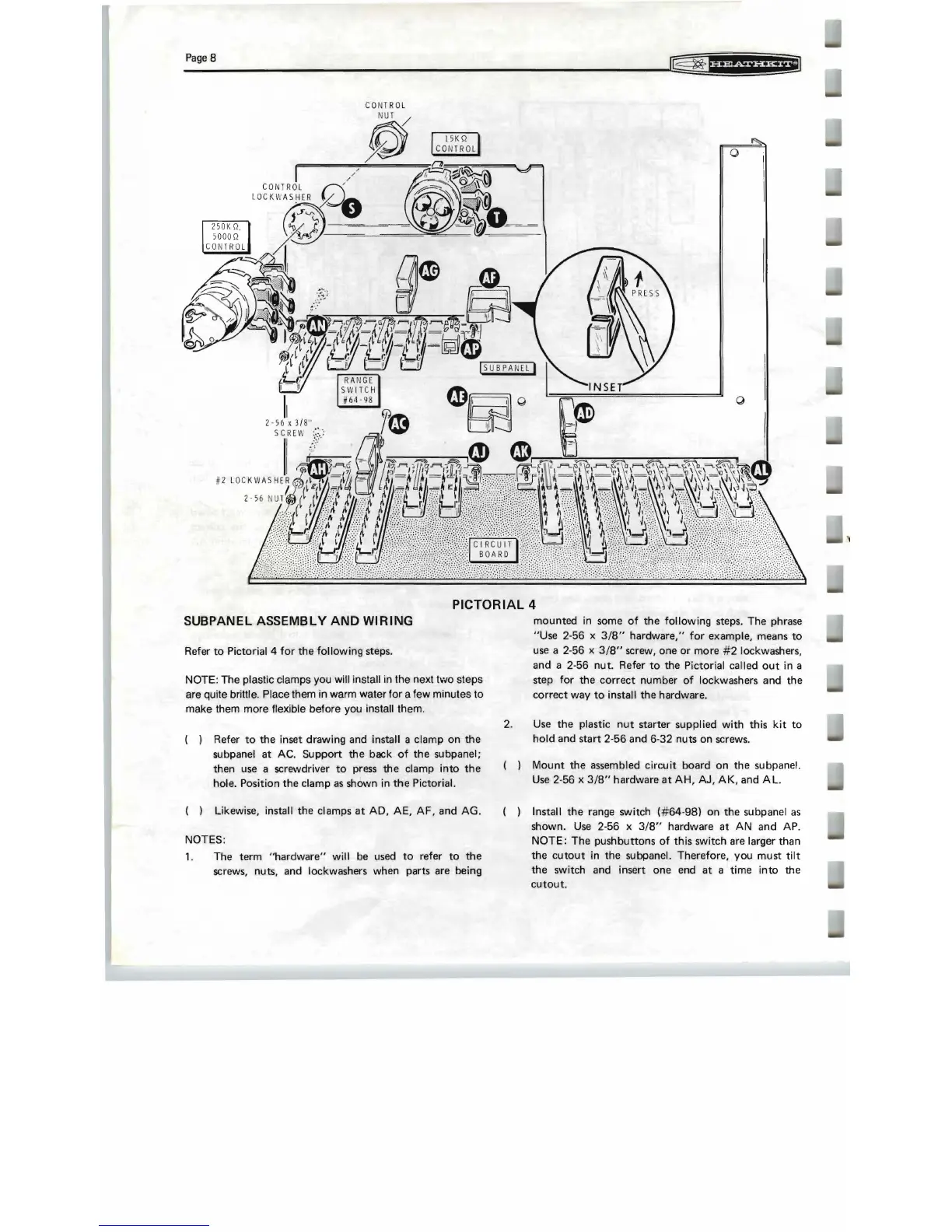
PICTORIAL 4
SUBPANEL ASSEMBLY AND WIRING
Refer
to
Pictorial 4
for
the
following
steps.
NOTE: The plastic clamps you will install in the next two steps
are quite brittle. Place them in warm water
for
a few minutes to
make them more flexjble before you install them.
( ) Refer
to
the inset drawing and install a clamp
on
the
subpanel at AC. Support the back
of
the subpanel;
then
use
a screwdriver
to
press
the clamp
into
the
hole. Position the clamp
as
shown in
the
Pictorial.
( ) Likewise, install the clamps
at
AD, AE,
AF,
and AG .
NOTES:
1. The term
"hardware"
will
be
used
to
refer
to
the
screws, nuts, and lockwashers when parts are being
mounted in some
of
the
following
steps. The phrase
"Use 2-56 x
3/8"
hardware,"
for
example, means
to
use
a 2-56 x
3/8"
screw, one
or
more
#2
lockwashers,
and a 2-56 nut. Refer
to
the Pictorial called
out
in a
step
for
the
correct
number
of
lockwashers and the
correct way
to
install the hardware.
2.
Use
the plastic
nut
starter suppl ied
with
this
kit
to
hold
and start 2-56 and 6-32 nuts on screws.
( )
Mount
the assembled
circuit
board on the subpanel.
Use
2-56 x
3/8"
hardware
at
AH,
AJ,
AK,
and
AL.
( ) Install the range switch
(#64-98)
on the subpanel
as
shown.
Use
2-56 x
3/8"
hardware at
AN
and AP.
NOTE:
The push
buttons
of
this switch are larger than
the
cutout
in the subpanel. Therefore, you must
tilt
the switch and insert one end at a time
into
the
cutout.