Page
5
~
~fh*iifHfj]
STEP-BY-STEP
ASSEMBLY
CONTINUE
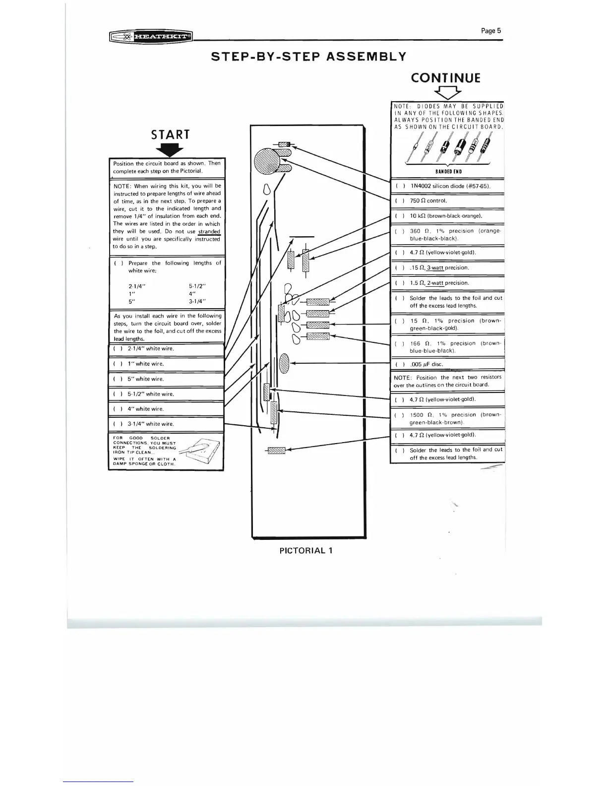
NOTE
DIODES MAY
BE
SUPPLIED
I
NAN
Y 0 F
THE
F 0 L
LOW
IN
G S HAP E S.
ALWAYS
POS
ITION
THE
BANDED
END
AS
SHOWN
ON
THE
CIRCUIT
BOARD.
START
Position
the
circu it board as shown. Then
complete each
step
on
the
Pictorial.
NOTE: When wiring this kit, you will be
instructed
to
prepare lengths of wire ahead
of time,
as
in
the
next
step. To prepare a
wire,
cut
it
to
the
indicated length
and
remove
1/4"
of insulation from each end.
The wires are listed
in
the
order
in
which
they will be used .
Do
not
use
~
wire until you are specifically instructed
to
do so
in
a step.
( ) Prepare
the
following lengths of
white wire;
2·
1/4"
1"
5"
5·1/2"
4"
3·1/4"
As
you install each wire
in
the following
steps, turn
the
circuit board over, solder
the
wire
to
the
foil, and
cut
off
the
excess
lead
1"
white wire.
5"
white wire.
5·1/2"
white
wire.
4"
white wire.
3·1/4"
white wire.
rOR
GOOD
SOLDER
CONNECTIONS
,
YOU
MUST
4tl
..
K(EP
THE
SOLDERING
~"
~~:
TII~
c~~~:~.
WITH
A -. _ _~ I
DAMP
SPONGE
OR
CLOTH
.
Il
lrlll
, v '
BANDED
END
1 N4002 silicon diode
(#57-65).
750 n control.
10
kn
(brown-black-orange).
360
n.
1%
precision
(o
range
·
blu
e-black-black)
.
4.7 n (Yellow-violet-gold).
.15
n,
3-
watt
precision.
1.5
n,
2-watt precision.
Solder the leads
to
the
foil and
cut
off
the
excess lead lengths.
( )
15
n.
1%
precision
(brown-
I'
green-black-gold)
.
166
n.
(brown-
over
the
outlines
on
the
circuit board.
4.7 n (yellow·violet·gold).
1500
n. 1%
precision
(brown-
green-black-brown)
.
4.7 n (yellow·violet-gold).
Solder
the
leads
to
the
foil and
cut
off
the excess lead lengths.
PICTORIAL
1