Page
20
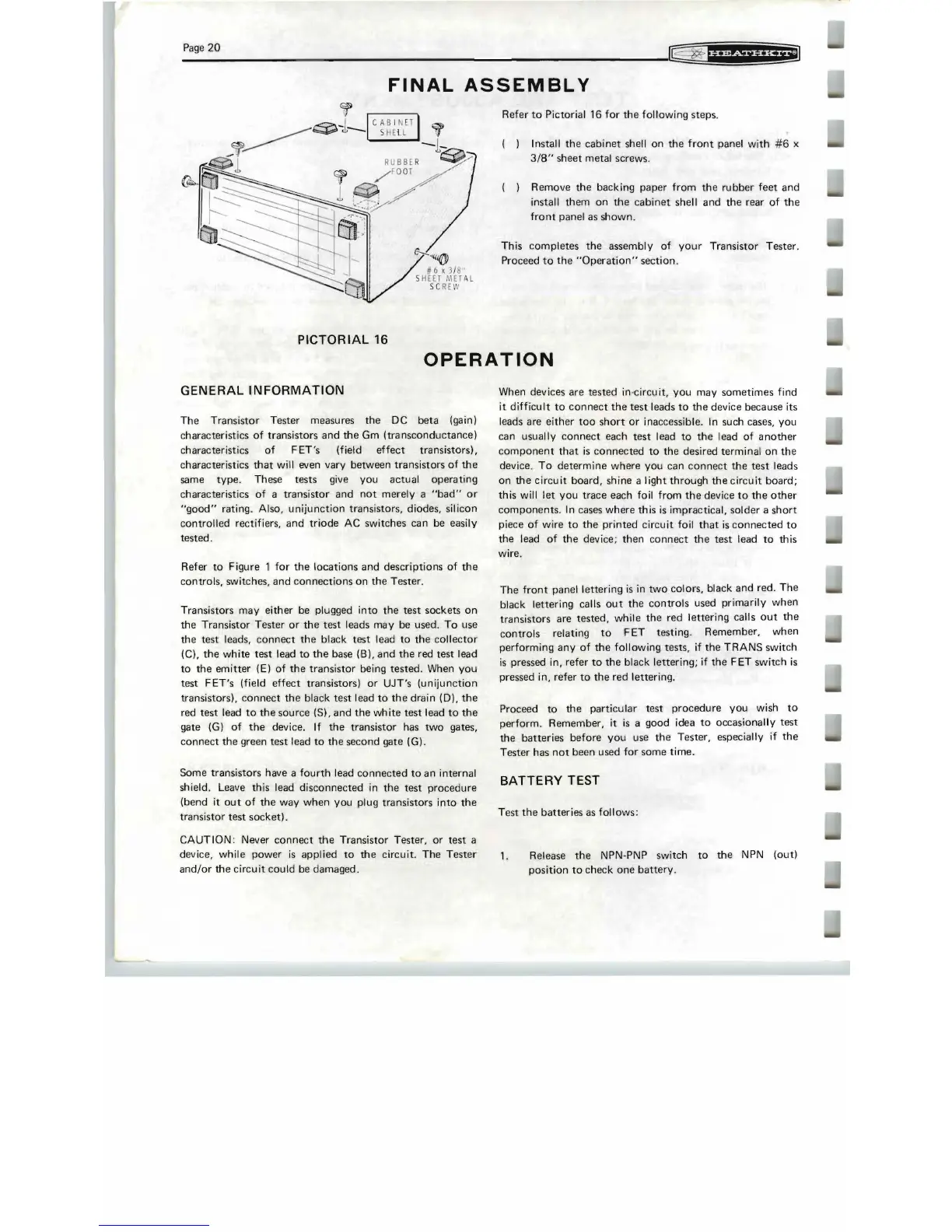
FINAL
ASSEMBLY
~"ii@
#6 , j 18
S
HEET
i.1
E1
AL
SC
REW
Refer
to
Pictorial 16 for
the
following steps.
Install
the
cabinet
shell on
the
front
panel
with
#6
x
3/8"
sheet
metal screws.
Remove
the
backing paper
from
the
rubber
feet
and
install them on
the
cabinet
shell
and
the
rear
of
the
front
panel as
shown.
This
completes
the
assembly
of
your
Transistor Tester.
Proceed
to
the
"Operation"
section.
PICTORIAL
16
OPERATION
GENERAL
INFORMATION
The
Transistor Tester measures
the
DC
beta
(gain)
characteristics
of
transistors
and
the
Gm
(transconductance)
characteristics
of
F ET's (field
effect
transistors),
characteristics
that
will even vary between transistors
of
the
same type. These
tests
give you actual
operating
characteristics
of
a
transistor
and
not
merely a
"bad"
or
"good"
rating. Also,
unijunction
transistors, diodes, silicon
control
·led rectifiers,
and
triode
AC switches can be easily
tested.
Refer
to
Figure 1
for
the
locations
and
descriptions
of
the
controls, switches,
and
connections
on
the
Tester
.
Transistors may
either
be plugged
into
the
test
sockets
on
the
Transistor Tester
or
the
test
leads may be used'.
To
use
the
test leads,
connect
the
black
test
lead
to
the
collector
(C),
the
white
test
lead
to
the
base (B),
and
the
red
test
I'ead
to
the
emitter
(E)
of
the
transistor
being
tested.
When
you
test
FET's
(field
effect
transistors)
or
UJT's
(unijunction
transistors),
connect
the
black
test
lead
to
the
drain
(0),
the
red
test
lead
to
the
source (S),
and
the
white
test
lead
to
the
gate
(G)
of
the
device.
If
the
transistor has
two
gates,
connect
the
green
test
lead
to
the
second gate (G).
Some transistors have a
fourth
lead
connected
to
an internal
shield. Leave this lead
disconnected
in
the
test
procedure
(bend it
out
of
the
way
when
you plug transistors
into
the
transistor
test
socket).
CAUTION: Never
connect
the
Transistor Tester,
or
test
a
device, while power
is
applied
to
the
circuit.
The
Tester
and/or
the
circuit
could be damaged.
When devices are tested
in
·circuit, you may
sometimes
find
it
difficult
to
connect
the
test
leads
to
the
device because its
leads are
either
too
short
or
inaccessible.
In
such cases, you
can usually
connect
each
test
lead
to
the
lead
of
another
component
that
is
connected
to
the
desired terminal on
the
device.
To
determine
where
you can
connect
the
test
leads
on
the
circuit
board, shine a light
through
the
circuit
board;
this will
let
you
trace
each foil from
the
device
to
the
other
components
.
In
cases
where
this
is
impractical, solder a
short
piece
of
wire
to
the
printed circuit foil
that
is
connected
to
the
lead
of
the
device;
then
connect
the
test
lead
to
this
wire.
The
front
panel lettering
is
in
two
colors, black
and
red.
The
black lettering catls
out
the
controls
used primarily
when
transistors are
tested,
while
the
red lettering calls
out
the
controls
relating
to
F ET testing. Remember, when
performing
any
of
the
following tests,
if
the
TRANS
switch
is
pressed in, refer
to
the
black lettering; if
the
FET
switch
is
pressed in, refer
to
the
red Ilettering.
Proceed
to
the
particular test
procedure
you wish
to
perform
. Remember, it
is
a good idea
to
occasionally
test
the
batteries
before
you
use
the
Tester, especially if
the
Tester has
not
been used for
some
time.
BATTERY
TEST
Test
the
batteries
as follows:
1.
Release
the
NPN-PNP switch
to
the
NPN (out)
position
to
check
one
battery.
 Loading...
