FINAL
WIRING
Refer
to
Pictorial 12 (on
Page
16)
for
the
following
steps.
( ) Connect the red wire
coming
from clamp
AD
to
the
positive
(+
) terminal
of
the meter (5-1).
Connect the black
wir
e coming
fr
om clamp
AD
to
the
negati
ve
(-)
terminal of the meter (5-1).
( ) Connect
the
black wire coming
fro
m clamp AG
to
the
lug
of
jack BB (5-3).
Connect
th
e w hite
wire
coming
from
clamp AG
to
the
lug
of
jack BC 15-4).
Connect the
wi
res coming
from
clamp
AF
as
follows:
Red
wire
to
the lug
of
jack BD (5-4) .
Green
wire
to
the lug
of
jack
BE
(5·2).
White-red
wire
to lug 1
of
batlery
holder
BG
(5-1
).
White·black wire to lug 2
of
battery
holder
BG
(5·1).
White·green wire
to
lug 1
of
battery
holder
BH (5·1).
White-gray
wire
to
lug 2
of
banery
holder
BH (5· 1).
Thi
s completes
the
wiring
of
yo
ur Transistor Tester.
Check
to
see
that
all connections are soldered.
Switches C and L should n
Ot
have any wires connected
to
the switch lugs.
Refer
to
Pictorial
13
f
or
the fol
lowing
steps.
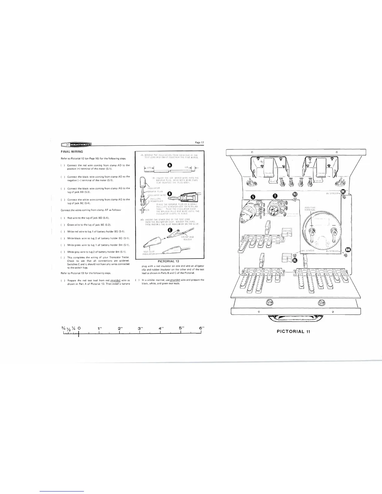
( ) Prepare the red t
es
t lead
from
red stranded
wire
as
shown in Part A
of
Pictorial 13. Then install a
ba
nana
%
Y2
~
0
1"
2"
I ! I I ! I II
Page
17
,AI
RfMOv[
Ul£ I " ".
'.H
ATlO""
tRO·\' [ACH
",'~D
Of
IHi
IISllE
~
D
A" O
1\
'
/1>
,
I
OC.[IHI~
IHE
fiN
E
Vi
I
RE
S .
r-lfL.j 0
ii'
--1
r-
"'==" aI'
1=
-
,8,
I';;[~IIHI
;Id'
."ID
">I
RE
1',10 I
HE
' I
SA"A.."
P,uG
B[\~
BOIH ,'
IIRE
fl·,
D\
I
I",
flAT
AGA
I '" I IHI PII!G
BOI)
Y.
I
G
hi='
I \ S
UlAIO
::?
O--
SOt
li
l\
'
,A
flU
t.J
..
I', IUI
AI
!')
L!
R!
o~
I /
PHIllI
PS
I ,
r.E'
.'
,
V",
V
IP
~
V
)\\
/ P
l;(E
IHI eA ',A:;A
PLU
G 0 ') A SMAlL
I
/,
P.H
l
llIP\
ICRHD.RI'iiR
'O R 5 1
Mil
A
.
11:
~
lOOl
Pv')H
THE
1~,SUU
dOR
DV{R
\
THE
SA ,,;1
It.
P
tutJ
A 'jD
I,'
.I~{
U'
.1
Il1H(
~
I . ;)UlATOP.
S·
,AP').
II
~
P'
. AC(
ICI
I
NSfRI
lHE
OIHER
INO
Of
TH[
I[ST
lEAD
INt
O
IHE
ALLIG
AT
OR
C
LI
P S
OlotR
IHE
LEAD.
t
HE
N It
<S
IA
ll
I H! CLIP I
NS
UL
AT
OR
01,
IH£
Cl
iP
.
G
-
-:'A--
~
/"
~
CR:II\'P AND
_
---
_~,
S
OL
DE
R
~
~
1
T
EllellP
~
1
~ ,'5
Ul
A
lO
R
--
/~
~
..
PICTORIAL
13
plug
with
a red insulator on one end and
an
alligator
clip
and rubber insulator on the other end of the test
lead
as
shown
in
Parts
Band
C
of
the Pictorial.
In a s
imilar
manner,
use
stranded wire and prepare the
black, white, and green test lead
s.
,\
-=-
,-
JiIh
-
~-
ii
[£
Q_
0 m
,-,--
~
i
'"
~
-
===--i
~
~
.~~
~
~
~
_
r7J
t
~
)
~~
-
·
~
~
®
Cf-:J
m
PO~illIV[
IER
II
1'
. AL
r~
~
\! ..
..
..
~
II
~
:.
I
.......
~
0 ")f1
1'1(.
[ K
®
- - - - -
--
.
)!)
.
~
o 0
~Q::
-
~
: .
;;:J7
3"
4"
5"
6"
I I I I
PICTORIAL
11