INSTALLATION
I'
The Transceiver should be placed where adequate air
circulation is present in the area of the heat sink, as there is
I'
appreciable heat generated by the final transistors.
FIXED STATION INSTALLATION
Figure
2-1
shows basic fixed station connections. Figure
2-2
(fold-out from Page 248) shows connections for various
PREPARE
EACH
END
AS
SHOWN
accessories that may be used with the Transceiver. Figure
2-3
(fold-out from Page 251) show the basic station
k~''7
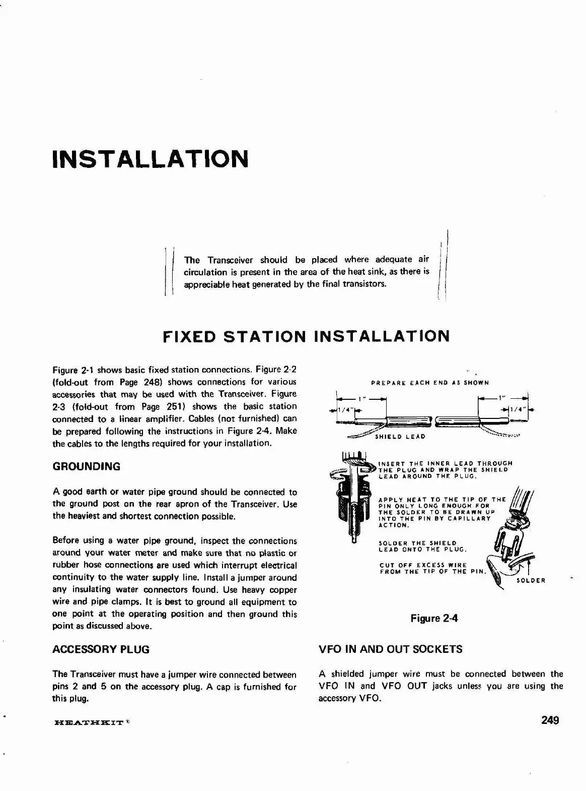
connected to a linear amplifier. Cables (not furnished) can
be
prepared following the instructions in Figure
24.
Make
the cables to the
lenaths reauired for your installation.
GROUNDING
A
good earth or water pipe ground should be connected to
the ground post on the rear apron of the Transceiver. Use
the heaviest and shortest connection possible.
Before using a water pip ground. inspect the connections
around your water meter and make sure that no plastic or
rubber hose connections are used which interrupt electrical
continuity to the water supply line.
Install a jumper around
any insulating water connectors found. Use heavy copper
wire and pipe clamps.
It
is best to ground all equipment to
one point at the operating position and then ground this
point as discussed above.
CUT
OFF EXCESS WIRE
FROM THE
TIP
OF THE
PIN.
SOLDER
Figure
2-4
ACCESSORY PLUG VFO
IN
AND
OUT SOCKETS
The Transceiver must have a jumper wire connected between
A
shielded jumper wire must be connected between the
pins
2
and 5 on the accessory plug.
A
cap
is
furnished for
VFO IN and VFO OUT jacks unless you are using the
this plug. accessory VFO.