Page
251
MICROPHONE CONNECTIONS
A high-impedance microphone equipped with a push-tetalk
witch should be used with the Transceiver
so
either the PTT
or VOX methods may be used to turn on the Transmitter.
A
two-pin microphone connector (Amphenol 80MC2M) is
furnished for this purpose. It should
he connected to the
microphonecable as directed in the following steps.
Heath
Microphones
(
1
Determine the desired length of your microphone
cable, and cut off any excess.
(
)
Perform the numbered steps in Figure
2-5.
Other Microphones
If you use a microphone different than the one shown,
connect the lead from the microphone element to pin 1 of
the panel connector. If the microphone has a
PTT
switch,
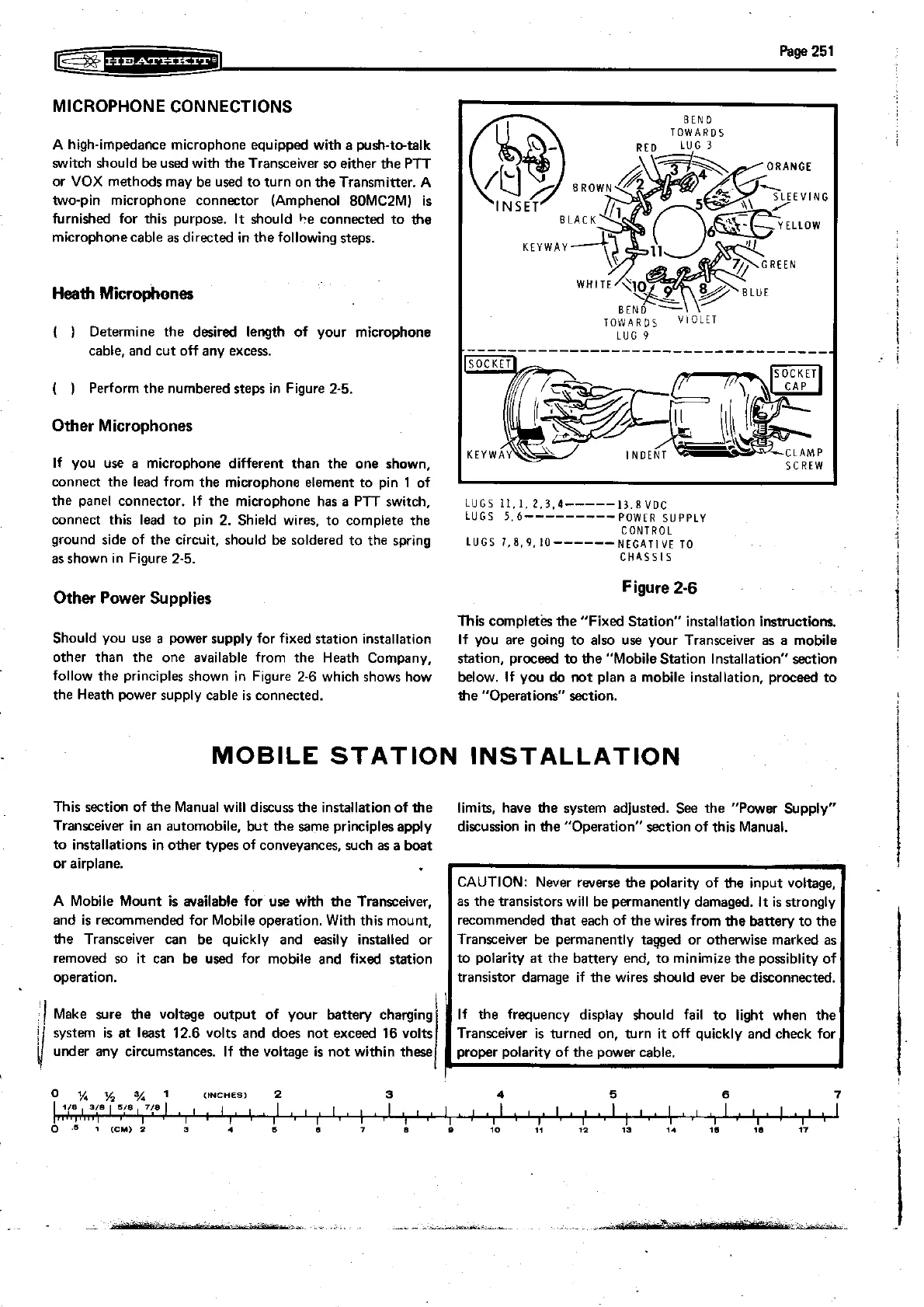
LUGS
11.1.
2.3.4-----13.8
voc
connect this lead to pin
2.
Shield wires, to complete the
5.6---------P0WER SUPPLY
CONTROL
ground side of the circuit, should be soldered to the spring
LUGS
~.~.~.I~------NEGATI~E
TO
as shown in Figure
2-5.
CHASSIS
LUG
9
..........................
Other Power Supplies
Figure
2-6
i
This completks the "Fixed Station" installation instructions.
Should you use
a
power supply for fixed station installation
If you are going to also use your Transceiver as a mobile
other than the one available from the Heath Company,
station, proceed
tothe "MobileStation lnstallation"section
follow the principles shown in F~gure
2-6
which shows how
below. If you
do
not plan a mobile installation, proceed to
the Heath power supply cable
is
connected.
the "Operations" section.
i
MOBILE STATION INSTALLATION
This section of the Manual will discuss
the
installation of the
limits, have the system adjusted. See the
"Power Supply"
Transceiver in an automobile, but the same principles apply
discussion in the "Operation" section of this Manual.
to installations in other types of conveyances, such as a boat
or airplane.
A Mobile Mount is available for
use
with the Transceiver.
and is recommended for Mobile operation. With this mount,
the Transceiver can be quickly and easily installed or
removed so
it
can be used for mobile and fixed station
operation.
'1
Make sure the voltage output of your battery charging
I
Y
system is
at
least 12.6 volts and does not exceed 16 volts
under any circumstances. If the voltage is not within these
I
CAUTION: Never reverse the polarity of the input voltage,
as the transistors will be permanently damaged.
It
is strongly
recommended that each of the wires from the battery to the
Transceiver be permanently tagged or otherwise marked as
to polarity at the battery end, to
minimize the possiblity of
transistor damage if the wires
should ever be disconnected.
If the frequency display should fail to light when the
Transceiver is turned on, turn
it
off quickly and check for
proper polarity of the power cable.