Page
273
TEST
CHART
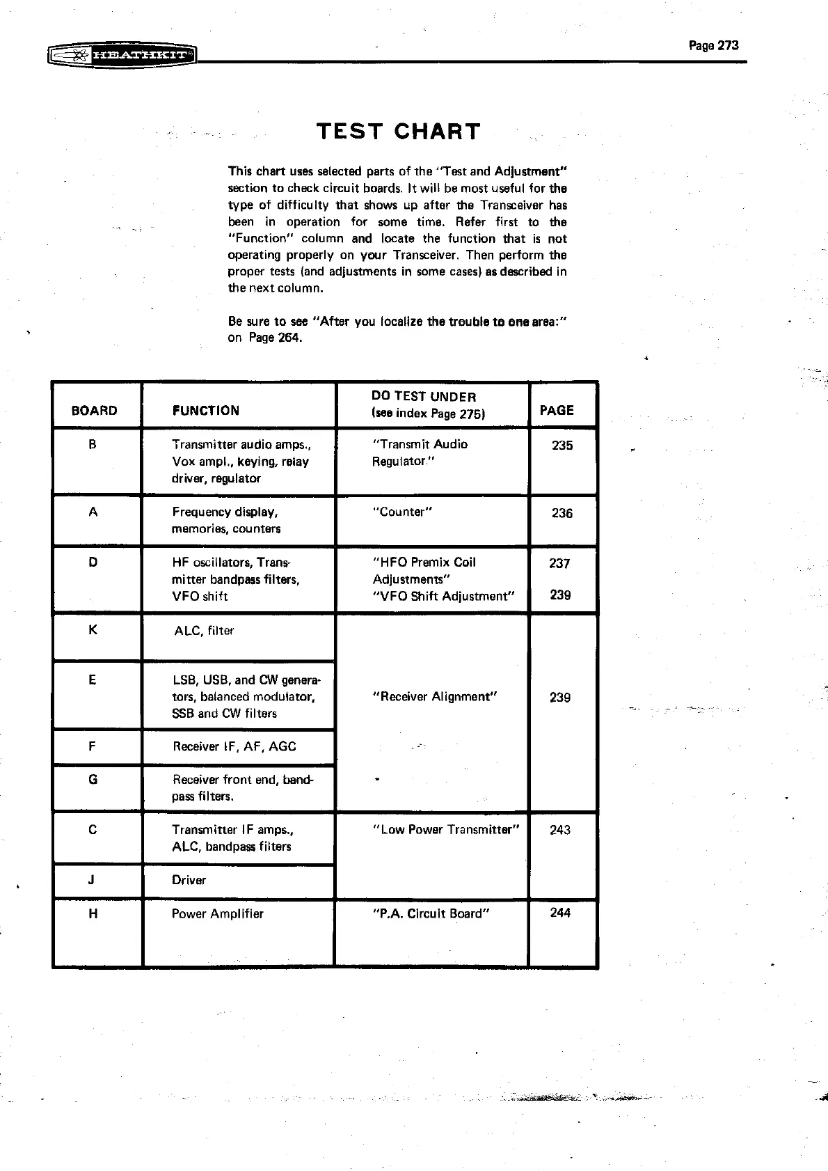
This chart uses selected parts of the "Test and Adjustment"
section to check circuit boards. It will be most useful for the
type of difficulty that shows up after the Transceiver has
.
.
~,
been in operation for some time. Refer first to the
"Function" column and locate the function that
is
not
operating properly on
ywr Transceiver. Then perform the
proper tests (and adjustments in some cases) as described in
the next column.
Be sure to
sse "After you localize the trouble to enearea:"
on Page
264.
Transmitter au "Transmit Audio
Vox ampl., keying, relay
"VFO Shift Ad'ustment"
"Receiver Alignment"
G
C
J
H
"Low Power Transmitter"
"P.A.
Circuit Board"
Receiver front end,
band-
pass filters.
Transmitter IF amps.,
ALC,
bandpass filters
Driver
Power Amplifier
243
244